Assembling a tube preamplifier. Homemade tube amplifier Pre-amplifier on tubes
There are people who absolutely cannot see the difference between film and digital photography, and there are people who absolutely cannot hear the difference between digital and analogue sound. It is very easy for such people to live, while others are constantly engaged in development and improvement, striving for perfection.
I would like to note right away that if you do not hear a difference in the sound of two different audio systems (or for you it is not a reason to change something), feel free to scroll further and under no circumstances go to the cat. Simply because you still won’t understand anything. For everyone else, welcome to the cat, where we will look at the simplest way to degrade digital sound.
So, let's go!
I will not retell the principles of operation of radio tubes and explain why they are so widely used not only in expensive reproducing equipment, but first of all, they are actively used by musicians and in recording studios. Radio tubes are loved for the unique distortions they introduce into the sound path.
The easiest and most affordable way to properly degrade the sound is to use a tube power PREAMP. It boosts the signal level and adds unique distortion that cannot be achieved in any other way. The circuit of tube amplifiers is quite simple and can be easily found on the Internet. The most important thing when assembling such an amplifier yourself is accuracy and precision. You can do it easier and buy a ready-made two-channel tube amplifier from China. In general, the Chinese are great, this device costing less than 2000 rubles is not at all embarrassing to connect even to a Hi-End audio system.
One of my acoustic systems is, of course, simpler, but partially made with my own hands. The speakers are assembled from components of car acoustics; the Pioneer A504r transistor amplifier, popular in the 90s, is used as the main power amplifier. And the sound source is the most ordinary iPhone, connected using a Lightning to Jack adapter and a regular interconnect cable with RCA connectors. As you know, there is no limit to perfection, so the assembled equipment is gradually changing in pursuit of worse sound.
Included with the tube preamplifier are 6J1 tubes (pictured on the left), an analogue of the Soviet 6Zh1 high-frequency pentodes. The sound with them certainly gets worse, but not enough. This is especially noticeable when listening to rock and jazz compositions. For experiments, I bought several modifications of Soviet radio tubes on Avito: 6Zh3P, 6Zh5P and 6Zh38P. Each lamp costs from 100 to 250 rubles, depending on its condition. Usually these are lamps from the 70s and 80s, brand new and unused.
The greatest effect of sound deterioration was achieved using high-frequency beam tetrodes - 6Zh5P. During operation, the lamps heat up to 65 degrees, and the sound with them is most interesting. But this is only true for certain genres. For example, with electronic music, the complete 6J1 sound better (that is, worse) than Soviet radio tubes. In general, it's all a matter of personal taste and you can't say that these lamps are better and others are worse.
To cause butthurt in those who had their ears trodden on by a bear as a child, the Chinese added two small red LEDs at the base of the radio tube ports. This is exclusively decorative lighting, because... not all types of lamps have their own visible glow during operation (for example, 6Zh5P do not glow at all, but they heat up more than others). But any sofa expert can say that the tubes in this amplifier are just for beauty :)
As a sound source - the fastest and at that time the most inexpensive iPhone in the SE version; such a device now costs less than 20 thousand rubles. I'm lucky that I have a device from Hong Kong with sound. To diversify this sound a little, I purchased an ingenious sound deteriorator in the form of a Lightning - Jack MMX62AM/A adapter. Its price is only 600 rubles and I can confidently say that this is the best opportunity to change the sound of any audio system with a minimum investment. Considering that inside this adapter there is a DAC, ADC and power amplifier, it’s generally surprising why it costs so little.
Chinese 6J1 radio tubes in operation.
Since we're talking about the entire audio system, we can also mention the interconnect cables. Everything here is also quite simple and depends solely on personal preferences. The evaluation criterion is very simple: like it or dislike it. As an interconnect cable between the preamplifier and the final amplifier, I personally prefer a blue cable from an unknown manufacturer with simple Belsis connectors. But to be honest, I didn’t like the Vention cable (pictured on the right).
The situation is reversed between the sound source and the tube preamplifier. The Chinese brand cable Vention, costing 350 rubles, sounds at least as good as the German Schulz Kabel costing 550 rubles. In general, you can even use aluminum hangers as wires, if you specifically like the sound (with interference, yay). But if you really don’t hear the difference between a 50-ruble interconnect with an outrageous level of interference and a normal speaker cable, you can only envy you that you have such an easy and simple life.
But if you notice a difference in sound when replacing certain components (from wires to speakers), then I can safely recommend such a tube amplifier as the most affordable way to worsen the sound using unique distortions characteristic only of radio tubes. Well, or you can try to assemble a tube preamplifier with your own hands, if, of course, you have time for this.
I’ll go listen to this spoiled warm tube sound and drink some tea.
Background:
While building a home audio system, I encountered difficulties. One of them is that my tube power amplifier, when connected to a source “directly,” gives a boring, compressed sound. Without “tops” and “bottoms”, just a protruding lower middle. Moreover, the film sound is good, but my music (black metal) plays poorly.
Obviously, loudness compensation is required. The purchase, in general, solved the problem, but the sound quality (in general) deteriorated. The preamp went to the mezzanine to gather dust.
I decided to use a tone block in my system instead of loudness compensation.
There are Chinese ones already assembled, for example, on two 6n1p and a kenotron: 
But I took this set from the website in Russia - a tube tone block-preamplifier based on a 6n2p-ev double triode.
For 4000 rubles I received (all parts are new):
1100+1100 rubles - Two sets of parts for assembling two mono channels.
1000 rubles - TAN 15-01, toroidal power anode-heat transformer.
130 rubles - Power supply board.
270 rubles - Choke D15N (50mA, 10H).
400 rubles - shipping (from St. Petersburg to Novosibirsk).
Parcel contents: 
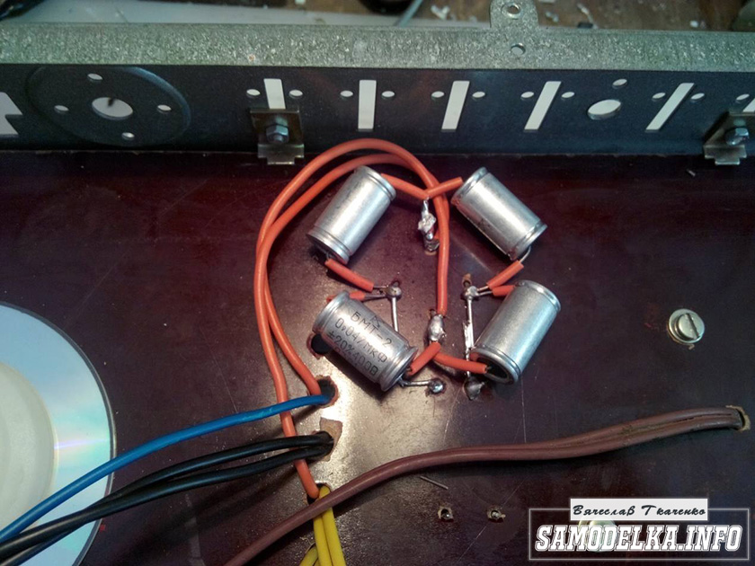
Close-up of the power supply components: 
A choke, and two double triodes 6n2p-ev - produced in 1972 and 1976 - which is strange. I thought they would be one year old. And these are structurally different even to the eye: 
(P.S.: The author wrote that all his lamps are from 1976. My 1972 got into his kit in some unknown way, and he didn’t put it in my car on purpose. I suggested listening to this for now. Didn't offer free lamp replacement. He did not apologize for the missing radio components. In general, the seller does not use any polite words (“thank you,” “hello,” “goodbye”) in correspondence, probably for reasons of principle).
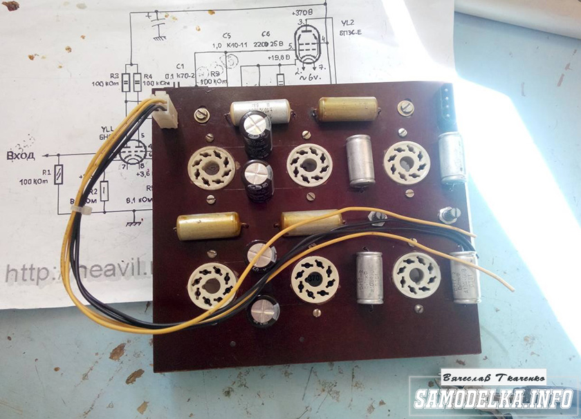
Preamp boards, two mono channels: 
Set of parts No. 1: 
Set of parts No. 2: 
“Manuscript” (Xerox copy in A4) with handwritten marks that I could not fully decipher. Just evaluate the level of performance: 
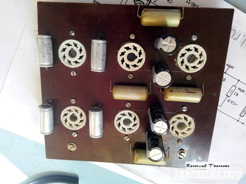
Almost soldered boards (differences from the original photo on the website are immediately visible - coupling capacitors and lamp sockets): 
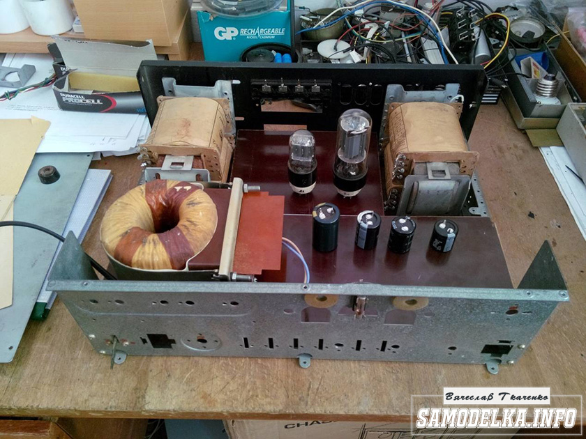
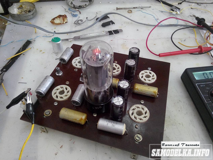
The amplifier was assembled on a breadboard (I apologize for the quality of the photos): 

Sound quality:
Average.
But the tone block, it seemed to me, was not quite optimally designed for high-quality speaker systems. A little “narrow” or something.
Adjustment within: ±8dB.
LF: 300 Hz.
HF: 3 kHz.
band: 20-20000Hz. (±0.3dB).
THD: 0.05%.
out: 2V、maximum 20V or more.
Because of this, the adjustment occurs in a limited range, which is clearly audible.
I would like adjustment LF: 100 Hz And HF: 10 kHz, and maybe even wider.
The seller said that the scheme suits many people. 
For low frequencies, he suggested replacing capacitors C3, replacing the original 15 nF with 10 nF, like Manakov’s.
For high frequencies, I suggested changing the 1 nF capacitor C1 (according to Manakov’s scheme, C2 by Matyushin) downwards.
Advantages:
Quite inexpensive.
Easy assembly.
Flaws:
You need two mono channels for the stereo option, which increases the inconvenience of adjustment, and twice the number of “twists”.
The instructions could have been more accurate.
The most common variable resistors are used, with characteristic “B”, so the timbres are not adjusted smoothly, but sharply, abruptly.
Complete radio components in the kit are the cheapest.
The kit was missing 4 resistors. The radio tubes were not paired.
There is no assembly diagram, so I could not assemble it correctly until I myself found an error in the markings applied to the board.
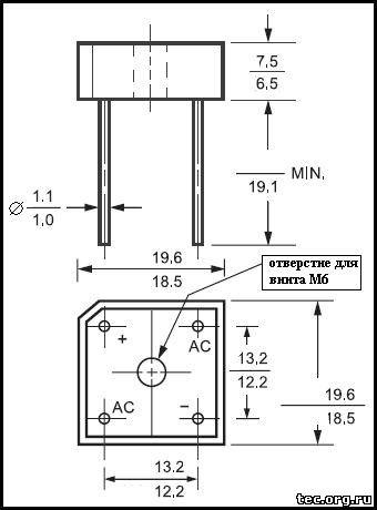
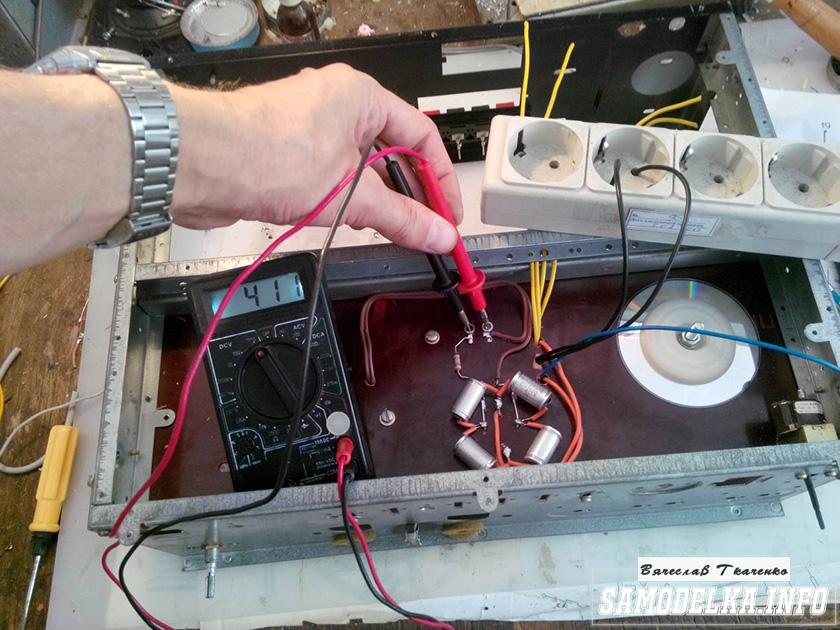
It turned out to be the exit block at the rear. It has reverse polarity compared to other pads on the board: 
In general, the scheme proposed by Matyushin is less successful than Manakov’s scheme.
Manakov’s circuit is much simpler, the gain is less (which is good), since Matyushin’s is redundant.
In addition, Matyushin’s circuit requires three expensive coupling capacitors per channel, instead of Manakov’s one.
P.S.
I decided to make a Manakov tone block from Matyushin’s tone block. According to the scheme, we remove the following elements: 
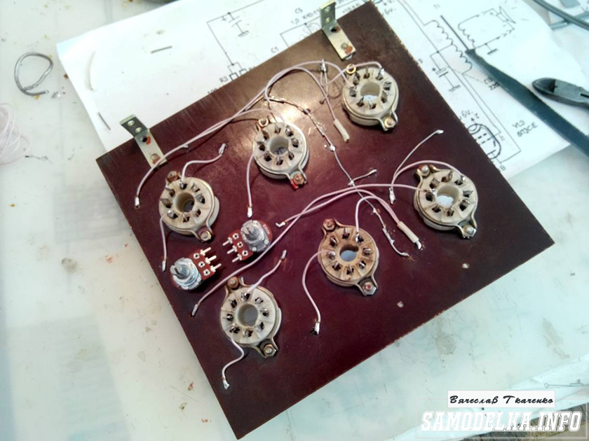
We get this type of board: 
The biggest influence on the sound quality of this preamplifier is the coupling capacitor and capacitor C2 in the tone block. I installed paper-oil K40U-2 (0.1 µF 350V) instead of film Wima, because I did not find anything more suitable. On C2 you need to put either high-voltage ceramic or mica. I installed SGM-1.
The sound quality has increased greatly compared to the original circuit, but the K40U-2 capacitor begins to sound good only after it has “warmed up” (at least half an hour). I don’t know what caused this, but it’s a fact.
P.P.S.
K40U-2 changed to polypropylene Taiwanese: 
The sound has changed compared to the K40U-2 - on my black metal the “middle” has become more dynamic and harsh. But at the same time, the sound became less “singing” and “soulful” on rock ballads, etc.
P.P.P.S.
A 6N2P-EV lamp can be replaced with a 6N1P-EV lamp without changing the circuit - just pulled out one and inserted another (as you can see, I also bypassed the electrolytes in the anodes with 1uF 250V film capacitors, I didn’t hear a difference, but let them be): 
The only difference I heard is that the 6N1P-EV plays a little quieter. Well, inside they are different in design: 
P.P.P.P.S.
As a result of my barbaric, random experiments, one of the two 6N2P-EV lamps fell victim. Interestingly, the newer lamp, from 1976, burned out.
Stay tuned.
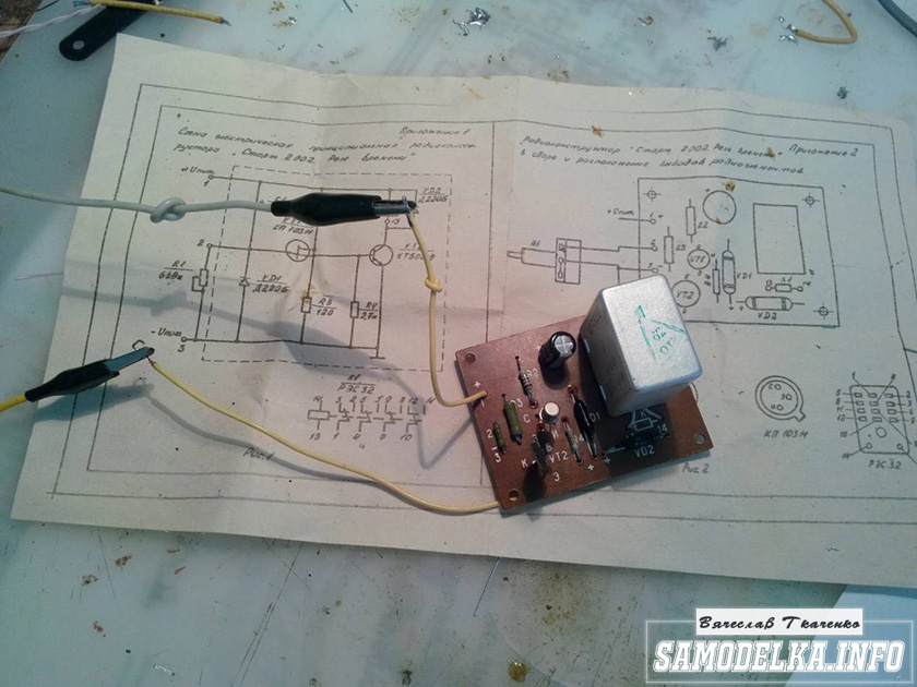
I'm planning to buy +12 Add to favorites I liked the review +26 +53This module preamp with an input switch was developed by the Frenchman JL. Vandersleyen to work with audiophile power amplifiers of any level. It is implemented on pentode 6Zh32P(analogous to EF86), allows you to connect up to four signal sources and provides amplification of 16 dB. A small switchable low-frequency correction allows you to compensate for the influence of the listening room.
The appearance of the structure is shown in the figure:

(Click to enlarge)
Amplifier specifications:
Frequency band (with 1dB ripple) 10 Hz - 100 kHz
Frequency band (at 0.1 dB ripple) 20 Hz - 50 kHz
Active equalization (see description) + 3 dB at 50 Hz
Rise time<2 мксек
Distortions<0,1% при амплитуде сигнала 1 В в полосе 100 Гц — 10 кГц (на частоте 1 кГц типичное значение 0,03%)
Maximum output signal ~30 V at distortion up to 2% (THD)
Feedback depth - 18 dB
Signal to noise ratio >90dB
Input impedance 50 kOhm
The output impedance of the amplifier itself is 5 kOhm
Circuit Output Impedance - 100K Logarithmic Potentiometer
Channel separation > 50 dB
Inputs - RCA
Power: 6V - 400 mA / 320 V DC - 7 mA
Dimensions 135 x 100 x 30 mm
Due to its fairly compact dimensions, the unit can be built into the chassis of a finished amplifier or used as a stand-alone device (with an external power supply).
Figure 1 shows the operating principle of the gain stage.

Part of the output signal is fed back to the input, in antiphase, to tightly control the circuit gain. Thus, 18 dB of negative feedback reduces overall gain from +34 dB to +16 dB while reducing the stage's inherent distortion.
Due to the reduced influence of the RC feedback circuit (C11, R31) at low frequencies, the circuit gain increases in this range. At the specified values of 220 kOhm and 3.3 nF, a gain increase of 3 dB is provided for frequencies below 100 Hz (see below in the text)
The preamplifier is implemented on pentode 6Zh32P, which was developed specifically for use in the input stages of tape recorders and is characterized by a low microphone effect and high linearity.
The lamp characteristic has excellent linearity at a bias voltage of -3 V, and an anode voltage of 50 V DC, the voltage on the second grid is 180 V, on the third - 0 V (characteristic highlighted in red):
 (Click to enlarge)
Schematic diagram
The pre-amplifier circuit is shown in the figure:
 (Click to enlarge)
One of the four inputs is selected by slide switch S1. The diagram does not indicate the values of resistors R1, R5, R9, R13; they are selected based on the required input sensitivity.
The input impedance of the amplifier is 50 kOhm. The relatively low input impedance of the lamp is reduced even further due to negative feedback. Therefore, the input resistance of the circuit is determined mainly by the value of resistor R19.
The lamp's own gain is 50, due to feedback it is reduced to 6.5.
The inherent distortion of the lamp due to the negative feedback decreased to 0.03% with a signal amplitude of 1V at the output.
note that lamp's own noise, due to feedback does not decrease, but in the selected modes they turn out to be very low: the signal to noise ratio exceeds 90 dB.
An RC circuit is added to the feedback circuit to compensate for the loss of low-frequency gain that typically occurs due to insufficient listening room volume. As stated at the beginning of the article, the rise is 3 dB for frequencies below 100 Hz.
If you do not need such a function, elements C11-C12, D1, K1-K2 can not be installed, and resistors R31-R32 can be replaced with jumpers.
Setting the Volume Control at the output of the preamplifier is optimal for minimizing
signal/noise ratio. In this case, the risk of putting the cascade into limiting mode is eliminated, since to obtain a maximum output signal amplitude of 30 V, an input signal with an amplitude of 4.6 V is needed! (a rare source is able to give it away)
Pre-amplifier power supply.
The filament voltage of the lamps is supplied to the contacts on the printed circuit board. Thanks to this, it is possible to connect the filaments in parallel, then a voltage of 6-6.3 V will be required with a current consumption of 400 mA. Or you can connect the filaments of both lamps in series, then you will need a voltage of 12V with a current of 200mA...
Based on the anode voltage, the amplifier consumes 7 mA. If you recalculate the value of resistor R33, you can power the amplifier with a voltage from 300 to 320 V DC.
To enable low frequency equalization, +24 VDC is required to drive two 12 V relays.
Pre-amplifier design
Printed circuit boards
All elements of the circuit, including input connectors, relays, flip switch, and volume control are mounted on printed circuit boards. (Fig. 5). All connections are made on connectors, with the exception of filament circuits, which are soldered directly into the board.
Main board
The circuit board has no special features; all circuit elements are mounted on it. First, 7 1.3 mm contacts are soldered (see photo of the design), then thirteen jumpers. The remaining remaining elements are installed in circuit number order, with the potentiometer and roller switch installed last.
The common wire (ground) is connected between the two dual RCA input jacks.
View of the board from the conductor side:
 (Click to enlarge)
Arrangement of elements on the board:
 (Click to enlarge)
Lamp board
The board is soldered into the main board of the amplifier using 5 mm contacts at an angle of 90 degrees.
The board drawing is shown in the figure below:
The arrangement of elements on the lamp board is shown in the figure:
Inclusion
To test the amplifier, you will need a power supply of 6 or 12 V for the filament circuits and 320 V for the anode voltage.
When first turned on, it is advisable to supply high voltage from a regulated source.
The control voltage values are indicated in the diagram.
When a signal with an amplitude of 300 mV is applied to the input, the output should have a signal with an amplitude of about 2 V.
To check the low frequency correction you will need a +24V source.
When the correction is turned on, the signal rises frequency 60Hz should be 3 dB.
Measurement results
The measurement results are presented in the oscillograms below.
The response of the amplifier to a pulse signal shows its good stability and short rise time of the edges:
 (Click to enlarge)
The cutoff frequency is approximately 140 kHz with a roll-off of -1 dB.
The distortion level at a signal level of 1 V is less than 0.03%.
The spectral distribution of harmonics and noise is presented in the spectrograms:
 (Click to enlarge)
Note that the spectrum is dominated by second harmonic. However, its level is lower -70 d B, which eliminates the “velvety” color (typical of tube amplifiers, the so-called warm sound) of the signal.
The task of any amplifier is to amplify the signal without making any changes to it.
This amp does it great!
The overall noise level of the amplifier before the volume control is -90 dB.
The graph shows the frequency response when the low-frequency correction circuit is turned on:
 (Click to enlarge)
Please note the low impact of correction on the amplifier's frequency response and phase response. The Baxandel tone block (a fairly classic design) has a much greater influence on the output signal.
Construction details.
Resistors:
R1, R2, R5, R6, R9. R10, R13, R14: selected according to the required sensitivity of the inputs (or jumpers)
R3, R4, R7, R8, R11, R12, R15, R16, R17, R18: 470 kOhm / 0.5 W / 1%
R19, R20: 47kOhm/1/0.5W/1%
R21, R22: 150 kOhm / 2 W / 5%
R23, R24: 100 kOhm/2 W/5%
R25, R26: 47 kOhm/2 W/5%
R27, R28: 1.2kOhm/1/0.5W/1%
R29, R30: 360 kOhm /0.5W/ 1%
R31, R32: 220 kOhm / 0.5 W / 1%
R33 1 kOhm/2 W/5%
Capacitors
C1, C2: 1uF/50V/5mm,
C3, C4: 1uF / 250V / 5mm,
C5, C6: 0.1uF/50V/5mm
C7, C8: 100uF/6.3V/3.5mm,
C9, C10: 470 nF / 400 V / 15 mm C11,
C12: 3.3nF/100V/5mm
C13: 10uF/400V/5mm
Miscellaneous:
Lamp: V1, V2 - 6Zh32P (EF86)
Diodes: D1-1N4007
Variable resistor: P1- 100 kOhm (Log/ALPS)
Relay: K1, K2 - SIL / Meder SIL12-1A72-71L
Galette switch: S1 - 5P/2C /Lorlin PT6422
Toggle switch: S2 - NKK B12AH
Connectors: RCA (dual) - 2 pcs., RCA (single) - 1 pc.
Conclusion
The pre-amplifier on the 6Zh32P tube turned out to be absolutely transparent for sound, without introducing tube “warmth” and “velvety”, with a stable gain and low noise level.
A small low-frequency correction allows you to compensate for the weakening of the signal in the low-frequency region by the listening room, and the compact dimensions of the design allow it to be built into a ready-made amplifier.
The article was prepared based on materials from the Electronique Pratique magazine.
Happy creativity!
Today we have a useful homemade product for connoisseurs of good sound: a high-quality tube amplifier made by yourself
Hello!
I decided to assemble a push-pull tube amplifier (my hands were really itching) from the parts I had accumulated over a long time: housing, lamps, sockets for them, transformers, etc.
I must say that I got all this stuff for free (you mean free of charge) and the cost of my new project will be 0.00 hryvnia, and if I need to buy something in addition, I’ll buy it for rubles (since I started my project in Ukraine, and I’ll finish already in Russia).
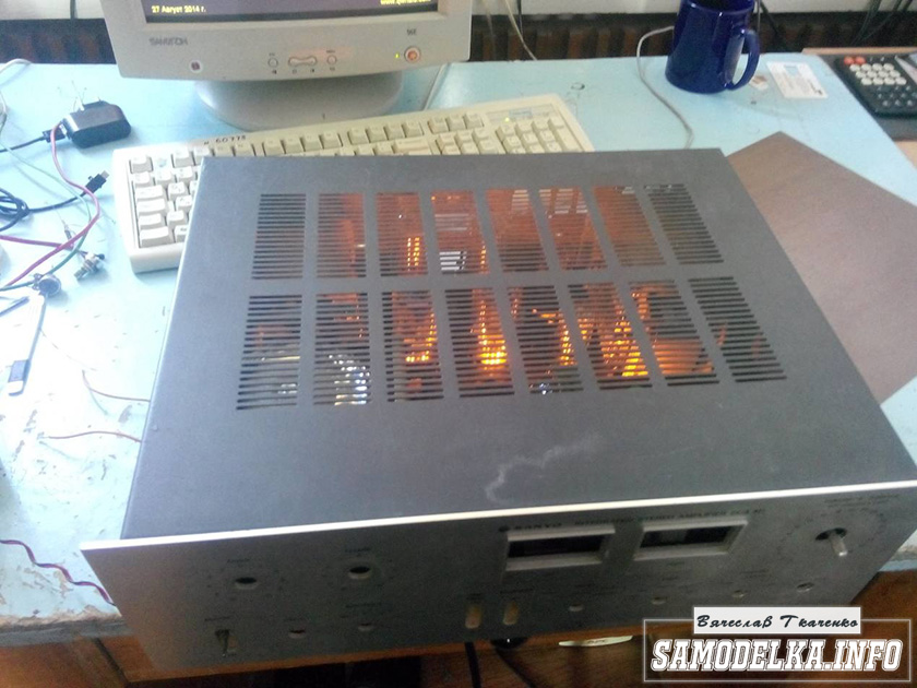
I'll start the description with the body.
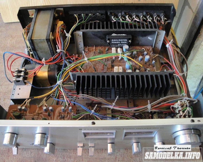
Once upon a time it was, apparently, a good amplifier from SANYO model DCA 411.
But I didn’t have a chance to listen to it because I got it in a terribly dirty and non-working state, it was dug up beyond repair and the burnt 110 V power supply (Japanese, probably) smoked all the insides. Instead of the original final stage microcircuits, there are some snot from Soviet transistors (this is a photo from the Internet of a good example). In short, I gutted it all out and began to think. So, I couldn’t think of anything better than stuffing a lamp there (there’s quite a lot of space there).

Decision is made. Now we need to decide on the scheme and details. I have a sufficient number of 6p3s and 6n9s lamps.


Due to the fact that I had already assembled a single-cycle amplifier for 6p3s, I wanted more power and, having rummaged through the Internet, I chose this push-pull amplifier circuit for 6p3s.
Circuit of a homemade tube amplifier (ULF)

The diagram is taken from the website heavil.ru
I must say that the scheme is probably not the best, but due to its relative simplicity and availability of parts, I decided to stick with it. Output transformer (an important figure in the plot).
It was decided to use the “legendary” TS-180 as output transformers. Don’t throw stones right away (save them for the end of the article :)) I myself have deep doubts about this decision, but given my desire not to spend a penny on this project, I will continue.
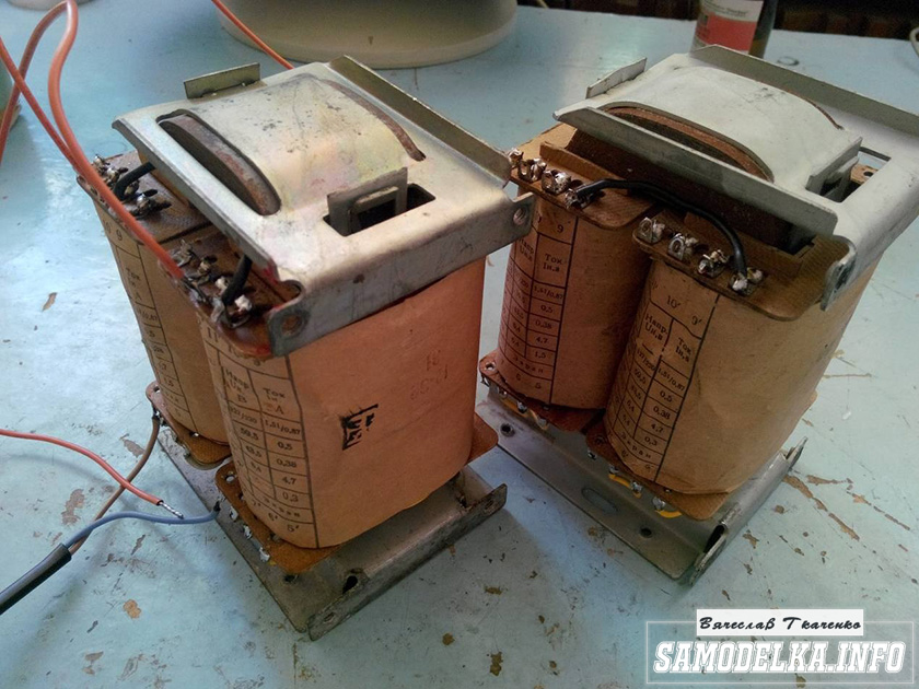
I connected the trance outputs for my case like this.
(8)—(7)(6)—(5)(2)—(1)(1′)—(2′)(5′)—(6′)(7′)—(8′) primary
(10)—(9)(9′)—(10′) secondary
anode voltage is applied to the connection of pins 1 and 1′, 8 and 8′ to the anodes of the lamps.
10 and 10′ per speaker. (I didn’t come up with this myself, I found it on the Internet). To dispel the fog of pessimism, I decided to check the frequency response of the transformer by eye. To do this, I quickly assembled such a stand.
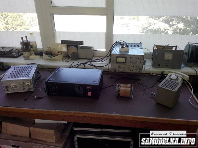
In the photo there is a GZ-102 generator, a BEAG APT-100 amplifier (100V-100W), an S1-65 oscilloscope, a 4 Ohm load equivalent (100W), and the transformer itself. By the way, there is a .
I set it to 1000 Hz with a swing of 80 (approximately) volts and record the voltage on the oscilloscope screen (about 2 V). Next, I increase the frequency and wait until the voltage on the trance secondary starts to drop. I do the same thing in the direction of decreasing the frequency.
The result, I must say, pleased me: the frequency response is almost linear in the range from 30 Hz to 16 kHz, well, I thought it would be much worse. By the way, the BEAG APT-100 amplifier has a step-up transformer at the output and its frequency response may also not be ideal.
Now you can collect everything in a heap into a case with a clear conscience. There is an idea to do the installation and layout inside in the best traditions of so-called modding (minimum wires in sight) and it would also be nice to have LED backlighting like in industrial copies.
Power supply for a homemade tube amplifier.
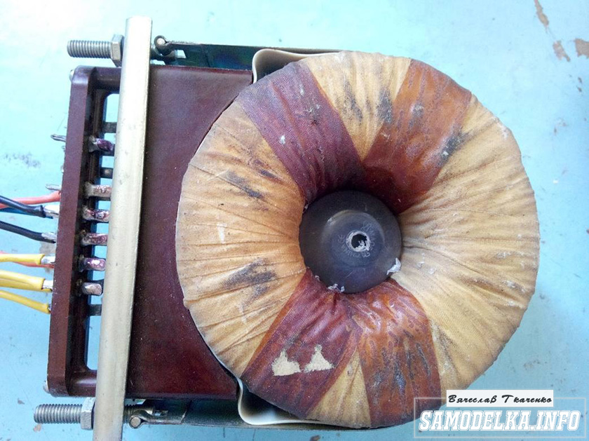
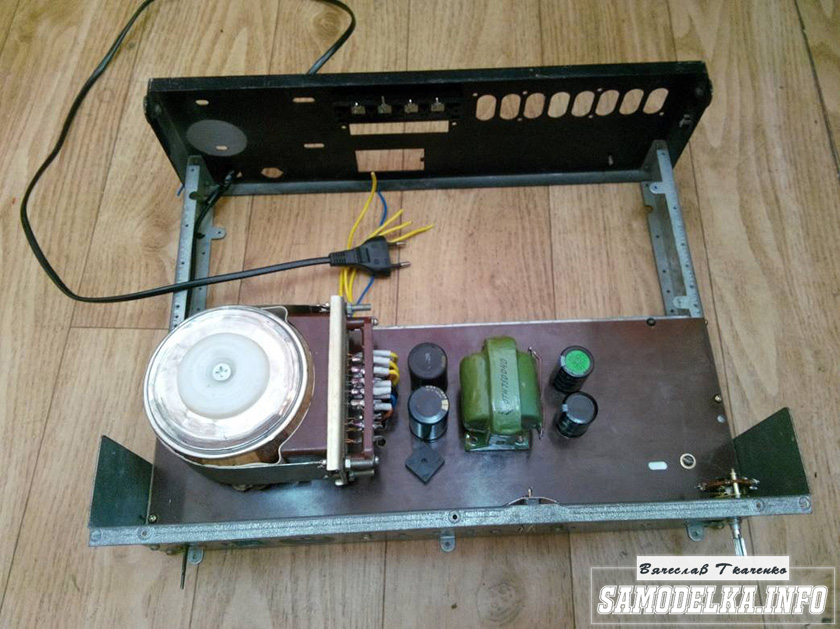
I'll start the assembly and at the same time describe it. The heart of the power supply (and of the entire amplifier, probably) will be the TST-143 toroidal transformer, which I once (4 years ago) tore out of some tube generator right as it was being taken to a landfill. Unfortunately, I didn’t manage to do anything else. It’s a pity for such a generator, but maybe it was still working or could have been repaired... Okay, I digress. Here he is my security officer.


Of course, I found a diagram for it on the Internet.

The rectifier will be on a diode bridge with a filter on the inductor for anode power. And 12 volts to power the backlight and anode voltage. This is the throttle I have.
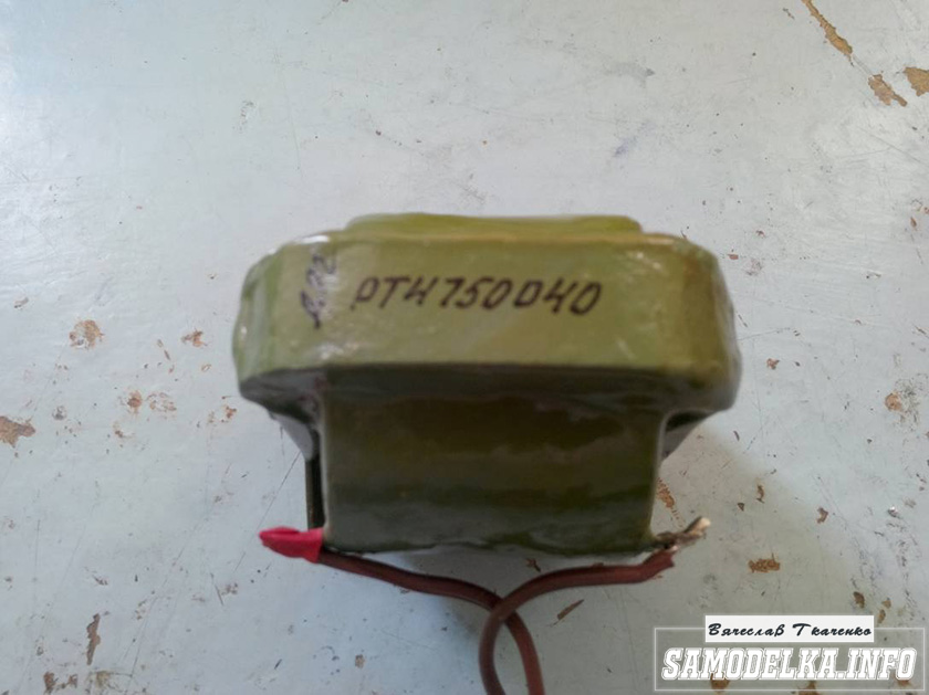
Its inductance was 5 henry (according to the device), which is quite enough for good filtration. And the diode bridge was found like this.
Its name is BR1010. (10 amps 1000 volts). I'm starting to cut out the amplifier. I think it will be something like this.
I mark and cut holes in the PCB for the sockets for the light bulbs.


It turns out well :) I like everything so far.

This way and that way. drill and saw :)

Something began to emerge.
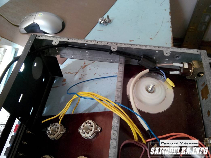
I found a fluoroplastic wire in old supplies and immediately all the alternatives and compromises regarding the wire for installation disappeared without a trace :) .

This is how the installation turned out. Everything seems to be “kosher”, the incandescence is intertwined, the ground is practically at one point. Should work.

It's time to fence in food. After checking and testing all the output windings of the trans, I soldered all the necessary wires to it and began installing it according to the accepted plan.

As you know, in our life it’s not easy to go anywhere without improvised materials: this is how the Kinder Surprise container came in handy.
And a Nescafe lid and an old CD


I tore out the circuit boards of TVs and monitors. All containers are at least 400 volts (I know that I should have more, but I don’t want to buy them).
I bridge the bridge with containers (whatever were on hand, I’ll probably change them later)
It’s a bit much, but oh well, it will sag under load :)
I use the standard power switch from the amplifier (clear and soft).
We're done with that. It turned out well :)
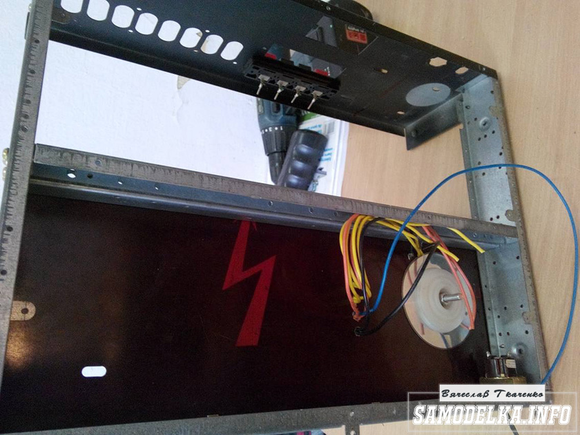
Backlight for tube amplifier housing.
To implement the backlight, an LED strip was purchased.
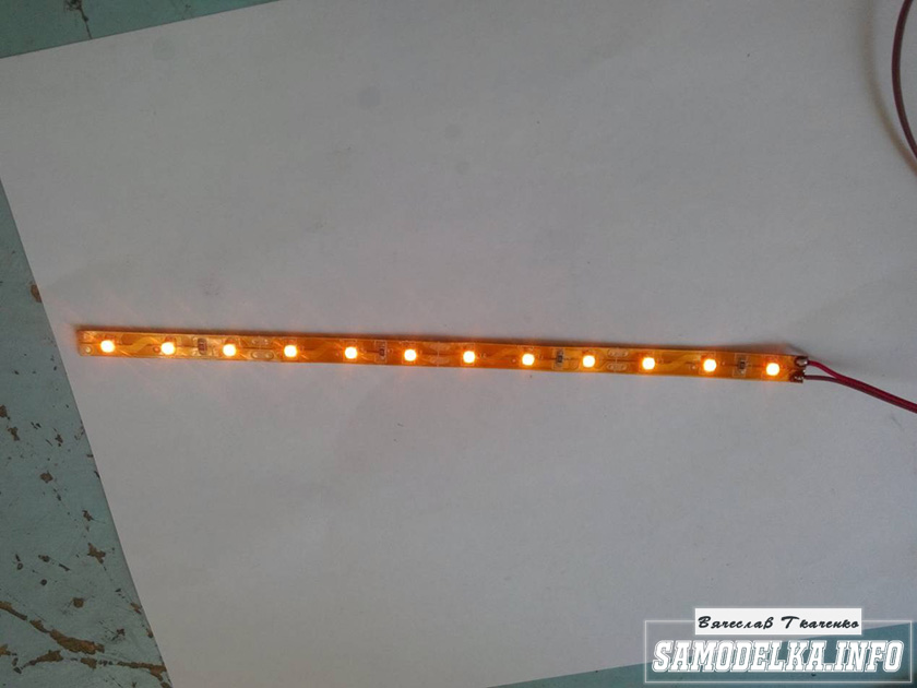
And installed in the housing as follows.

Now the glow of the amplifier will be visible during the daytime. To power the backlight, I will make a separate rectifier with a stabilizer on some KRKEN-like microcircuit (which I can find in the trash), from which I plan to power the anode voltage supply delay circuit.
Delay relay.
Having rummaged through the bins of my homeland, I found this completely untouched thing.
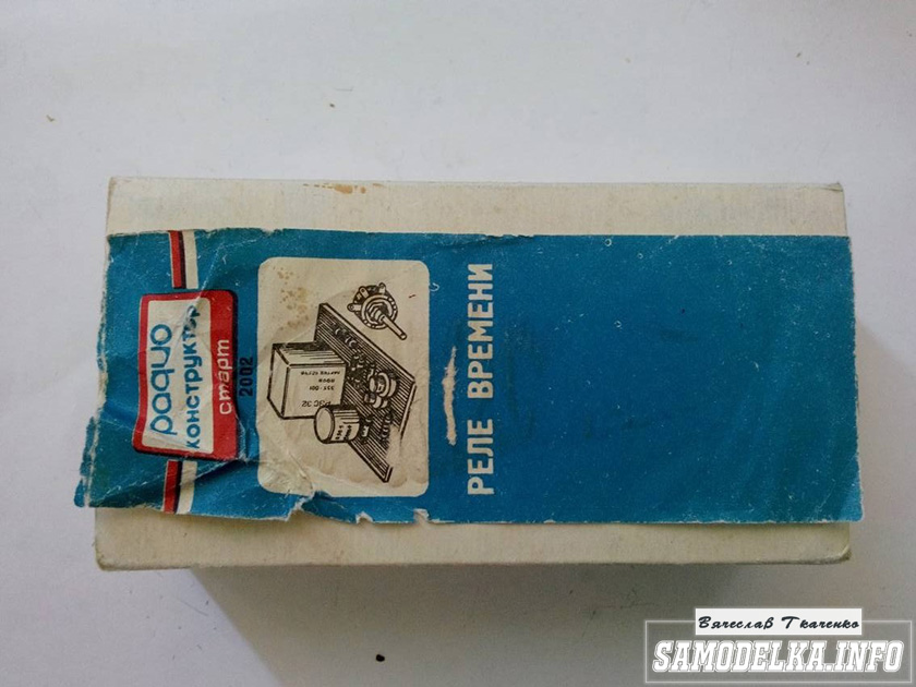
This is a radio time relay designer for a photo enlarger.
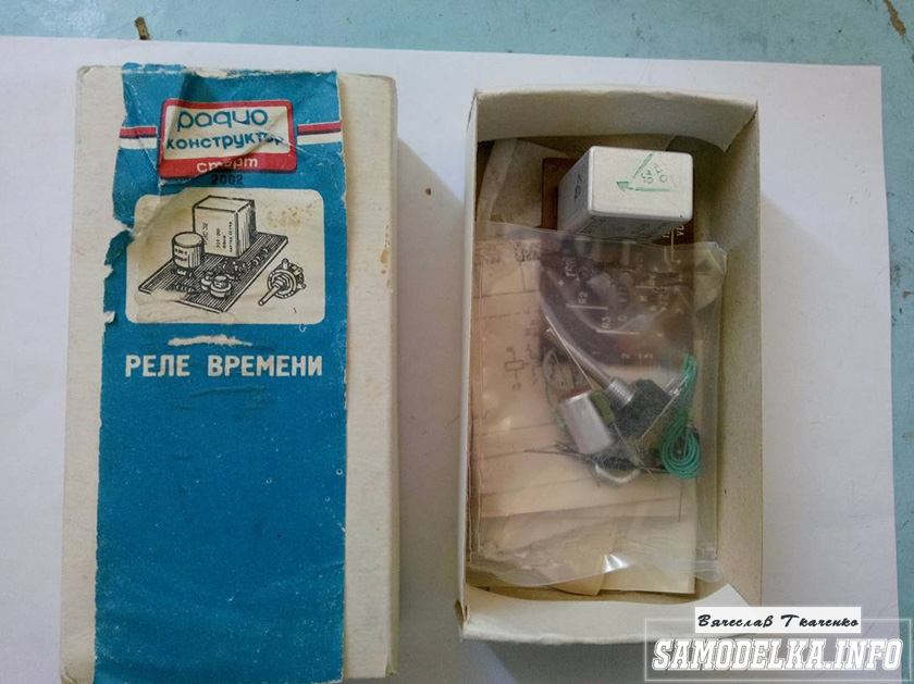

We collect, check, try on.


I set the response time to about 40 seconds, and replaced the variable resistor with a constant one. The matter is coming to an end. All that remains is to put everything together, install the face, indicators and regulators.
Regulators (input variables)
They say the sound quality can greatly depend on them. In short, I installed these
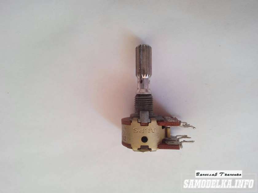
Dual 100 kOhm. Since I have two of them, I decided to parallel the pins, thereby obtaining 50 kOhm and increased resistance to wheezing :)
Indicators.
I used standard indicators, with standard backlighting

I mercilessly copied the connection diagram from the original board and used it as well.

This is what I ended up with.


When checking the power, the amplifier demonstrated an output voltage of 10 volts of an undistorted sine wave with a frequency of 1000 Hz into a 4 ohm load (25 watts) equally across channels, which was pleasing :)
When listening, the sound was crystal clear without background and dust, as they say, but too monitory, or what? beautiful, but flat.
I naively believed that he would play without timbres, but...
Using a software equalizer, we managed to get a very beautiful sound that everyone liked. Thank you all very much!!!
Good afternoon
Measurements are a long process, but processing the results and processing them takes even longer. But I still found the opportunity to prepare several graphs, at least for one separate scheme.
Attention: I'm slow: I rarely write here, most often when I want to take time off from work)). And everything new and interesting, invariably fresh, immediately ends up on Instagram. Click HERE, go to my account and subscribe :) I will always be very glad to see you! Enjoy reading:)
Note: described tube voltage amplifier module
(his photo is at the very bottom)
, while lying idle and leisurely looking for a new owner). If suddenly you are interested in it, write to me in the comments, or on social networks (links to them are at the end of the article). There are also a couple of extra empty boards :)
Experimental scheme:

This is a tube cascade with a common cathode and a current source in the anode. It differs favorably from the very common circuit with a resistor in the anode by the ability to change the lamp modes over a much wider range, more precisely tuning it to the task, and in the end obtain results unattainable for a conventional lamp resistive cascade.
The circuit contains a 6N1P lamp - a worthy and affordable representative of the lamp fraternity. If you believe the forums and reviews of some lamp lovers, its main drawback is its low price and availability for sale in very large quantities. Due to its lack of elitism and uniqueness, it is often declared unsuitable for sound :).
However, the light did not converge on the 6N1P, and any other triode can be installed in the circuit. 6N23P, 6N6P, 6N2P, 6N8S, etc... everyone can choose a lamp to suit their taste). All you need to do is change resistor R3 and adjust the current source with resistor R6.
By the way, a 6N23P lamp works very well with a current source in the anode. Especially at low supply voltages. In any case, much better than at the same voltages, but with an anode resistor. I’ve been wanting to publish this data as a separate article for two months now, but it just doesn’t work out :(.
Added 08/22/2018: Finally, after a long delay, a record about 6N23P appeared. Schemes, measurement results and comparisons at the link.
Let's return to the 6N1P lamp:
Measurements were taken for nine cases. Quiescent current ( Ia), took one of three values: 4.2 mA, 7.0 mA, 9.0 mA. For each of them, measurements were repeated with three load values Rн: 10 kOhm, 50 kOhm, 100 kOhm. For all combinations Ia And Rн Distortion spectra were taken at five different output signal levels ( Uout.amp.): 2.5 V, 5 V, 10 V, 20 V, 40 V (amplitude values).
Values Rн And Uout.amp. selected to be those that are or can be found in our hybrid and pure tube amplifiers. The anode current is limited above by the permissible power of the lamp. Below, there is no limitation as such, but at values less than 4 mA, distortions in all measurements have a long spectrum, and therefore have no practical value for us and are contraindicated for use.
I compiled all the results into graphs, and they, in turn, were collected into one large picture :). The rows are grouped by load resistance, the columns by quiescent current. Distortion spectra for different output signal levels are drawn in different colors. Perhaps this design is overloaded and not very convenient for perception, but it better demonstrates the main patterns.

Note: in a conventional cascade (with a resistor in the anode), due to the fact that the quiescent current and the lamp load resistance are tightly coupled, the modes corresponding to the bottom two rows of the graphs are not available. You will have to be content with modes close to the top three, or lower the anode current.
And here is a link to the results presented in table form
A little about what is visible here:
In general, I only wanted to show the results and leave the conclusions outside the article. In the end, everyone can make them themselves :). But after reflection, I still considered it necessary to identify some obvious patterns:
1. As expected, the distortion level drops as the load resistance increases. But the higher the lamp anode current (and with it its steepness), the less noticeable the effect of the load on distortion. Therefore, in hybrid amplifiers in which a semiconductor circuit with a low input impedance is connected to the output of a tube preamplifier, it is necessary to increase the anode current of the tube.
2. You can look at the situation from a different angle: the anode current greatly affects the level and spectrum of distortion, but the higher the load resistance, the less noticeable this influence is. Those. In pure tube circuits, where the load resistance may be very high, the plate current can be reduced without worrying too much about linearity problems.
3. The graphs clearly show that when working with output signal amplitudes up to 20 V, the 6N1P lamp in almost all modes has a beautiful low-level spectrum and is therefore well suited for hybrid power amplifiers and excellent for headphones.
Some other numbers:
I was no less interested in the voltage gain, its dependence on the selected anode current and load resistance. For clarity, I again summarized the results in a graph:

Conclusion: the required coefficient. The gains can be easily adjusted by changing the load resistor and the anode current. However, so that the linearity of the cascade does not suffer, it is worth checking the graphs of the distortion spectra when choosing the current and load.
It is also worth paying attention to the fact that as the quiescent current increases, the lamp bias voltage (voltage across resistor R3) decreases. And along with them the permissible input signal level. The bias voltages and the corresponding resistance of resistor R3 are summarized in a graph:
