ABS sensor resistance. Problems with ABS? We'll show you how to check the ABS sensor! How to check if the abs sensor is working
Automakers strive to make their products as safe as possible, for this purpose in sedans, hatchbacks, crossovers, etc. additional systems and components are installed. These modules also include ABS, which allows you to ensure the straightness of the vehicle during sudden braking on difficult road surfaces.
With frequent use, individual elements wear out, and diagnostic work has to be carried out to identify breakdowns. Let's figure out how to check the ABS sensor with a tester in various cars, because it is used to read electronic impulses transmitted to the ECU (electronic control unit).
The sensor operates in conjunction with a special toothed comb and is an induction coil. The information is analyzed in the ECU, and as a result, the pressure on the brake cylinders is adjusted through the hydraulic system.
The most common malfunctions that occur in these units are associated with an open circuit between the control unit and the sensor itself. Also the unit may fail due to mechanical or electrical damage, in this case, the pulse is incorrectly transmitted to the ECU.
ABS sensor
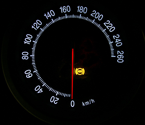
Possible problems are indicated by a special light sensor on the dashboard. For more accurate diagnosis, it is necessary to use special devices.
troubleshooting
The ABS sensor is checked by the tester independently after the indicator lights up. You will also need a vehicle operating manual and an assistant. The contacts with the necessary PIN connectors are first output.

The work is performed in the following sequence:
- the car is lifted using a jack or hung on a special lift;
- for ease of access to the sensor, the wheel is dismantled;
- on the back side of the hub, unscrew the fasteners that secure the required unit;
- we get rid of the casing on the ABS block and disconnect the connections to the controllers in it;
- We put a repair cable with PIN contacts on the tester, and connect the other end to the sensor socket;
- measure the resistance on the contacts and compare the readings with the factory parameters specified in the car’s operating instructions;
- test the wiring to make sure there is no short circuit to ground.

After this work, we turn the wheel by hand and measure the resistance. This operation requires someone's help. As the wheel speed changes, the data on the multimeter should also vary and respond to that speed.
The resistance of the ABS sensor is usually around 1 kOhm (1000 Ohm). It depends on the specific car model, since everyone has different sensors. So, for example, for one model the norm will be 600 Ohms, and for another 1350 Ohms.
Performing a voltage test
Monitoring the performance of sensors can be done using the “voltmeter” mode on a multimeter. The operation is carried out on each of the sensors in turn. To do this, you need to perform the following algorithm:
- alternately jack up the required side with the wheel;
- PIN cable connectors connect to the tester;
- the wheel will need to be rotated at the most accurate frequency of 1 rpm.

The multimeter should show readings in the range of 0.25-1.20 V. As the rotation speed increases, there should be a noticeable tendency for the voltage reading on the tester screen to increase.
Alternative verification methods
In addition to a multimeter, testing can be carried out using a more informative device for this purpose, for example, an oscilloscope. It forms a graph on the monitor, the amplitude of which determines the resistance level. However, this device is quite expensive for home use and requires qualified service by a specialist.
An oscilloscope can be found at specialized stations that professionally diagnose cars.
Many ABS systems in modern cars have a self-diagnosis function. By activating this function, the driver will receive a special error code on the on-board computer monitor, encrypted using numbers and letters. The operating instructions for this car model will help you understand the decoding.

Oscilloscope operation
You can replace a faulty sensor yourself. Before the procedure, you must order this item from an authorized dealer.
The updated sensor must be tested on a flat section of the road, braking at a speed of 20-40 km/h. To do this, the brake pedal must be sharply pressed to the floor. When operating correctly, a slight vibration transmitted from the operating unit will be felt under the driver’s foot on the pedal. You should also hear the characteristic sound of the pads braking. If necessary, the wiring is also replaced. As a result, there should be the same system testing results.
Anti-lock brakes are present on almost all modern cars. This is due to high safety requirements, since ABS provides real assistance in case of emergency braking and difficult road conditions. Important elements of the system are sensors that record the speed of rotation of the wheels. Despite its high reliability and ability to work for a long time, the device sometimes breaks down.
Purpose and principle of operation of the ABS sensor
Anti-lock braking systems appeared on cars in the 70s, significantly increasing their safety during emergency braking. ABS consists of a control unit, a hydraulic unit, wheel brakes and speed sensors. The main device of the system is the control unit, into which sensor signals are received and processed. The data is analyzed and a decision is made to slow down or accelerate the wheels in the form of a signal to the valves of the hydraulic unit, which acts as a control.
When you press the brake pedal hard, the sensor detects that the wheel is locked and sends a signal to reduce the braking force, after which the brake fluid pressure drops and the wheel unlocks. If the brake pads are not released, the process will be repeated until the desired result is achieved. Thus, the operation of ABS is a cycle: braking - analysis - braking. The sensor itself controls the speed of rotation of the wheel.

The system is activated instantly, even before the wheel locks, which is indicated by the receipt of a signal on the instrument panel and is felt by characteristic shocks in the brake pedal. If a breakdown occurs, the brake system remains operational and operates normally.
Signs of a malfunctioning ABS sensor
The first sign of an ABS malfunction is a lit indicator on the instrument panel that does not go out for more than 6 seconds after turning on the ignition, or does not turn on when driving. A system breakdown is detected when the vehicle is moving at a speed of more than 25 km/h. There are quite a few problems that can happen with the anti-lock braking system, but the most common ones include the following:
- ABS sensor wire is broken or the controller unit is damaged. In this case, an error is displayed on the instrument panel, the system is turned off, and signals about changes in angular velocities are not given.
- The wheel sensor of the system has failed. When turned on, the system performs self-diagnosis and detects an error, but continues to function. The cause of the breakdown may be oxidation of the contacts, poor power supply to the sensor and a short circuit to ground.
- Receipt from an additional device of information about different angular speeds of wheels at different tire pressures or different tread patterns, when the wheels brake differently.
- Mechanical failure of elements - hub bearings, play and fracture of the rotor on the wheel sensor. In case of such failures, the system does not start. This also includes ABS pump failure.

The most vulnerable element of the system is the wheel sensor, which is located next to the rotating hub and axle shaft. Exposure to dirt and play in the hub bearings can damage the device, completely blocking the operation of the ABS. Along with the indicator signal on the instrument panel, the following signs indicate a sensor failure:
- The on-board computer displays an ABS system error code.
- There is no characteristic vibration or sound when pressing the brake pedal.
- The wheels lock during emergency braking.
- Appearance of the parking brake signal when it is disabled.
Checking the ABS sensor
If the ABS sensor malfunctions, the control unit stops receiving commands and the system stops working, which is determined by the wheels locking when braking. Possible malfunctions of the device are determined by the tester. To do this, you need the tester itself, a soldering iron and pins for repairs. The pins are connected to the connectors, and the device measures the resistance of the ABS sensor, which must correspond to the parameters specified in the operating manual.

If there is no resistance, then there is a short circuit in the circuit; if it tends to infinity, then there is an open circuit in the circuit. Full diagnostics of the sensor is carried out by ringing all its wiring, since one of the reasons for malfunctions is a violation of the integrity of the wires. A working device has the following indicators:
- Insulation resistance – more than 20 kOhm.
- Leg – front right ABS sensor, resistance from 7 to 25 kOhm.
- Leg – rear right ABS sensor, resistance from 6 to 24 kOhm.
The sensors can also be checked in voltmeter mode. Each sensor is tested in turn using the following algorithm:
- After jacking up the required wheel, connect the connectors of the PIN cable to the tester.
- The wheel rotates at a frequency of 1 rpm.
A working sensor should give readings within 0.25-1.2 V. Increasing the wheel speed should increase the voltage reading. More informative information when testing the sensor can be obtained using an oscilloscope, but the device is quite expensive and requires special knowledge and conditions for maintenance.
ABS sensor repair

If a faulty ABS sensor is detected, it is dismantled, after which the issue of replacement or repair is decided. The cost of the device is quite high, and often there is a long wait for its delivery, which makes repairs quite feasible. The work is performed in the following order:

1. The sensor is disassembled by cutting off the part in which the measuring coil is located with a hacksaw. The body is carefully filed in a circle so as not to damage the fasteners.

2. The plastic casing protecting the coil is removed using a sharp knife and the winding is unwinded from the frame.

3. Wind a new coil with a wire of the same diameter. The RES-8 relay winding is suitable for this. The number of windings must provide the required resistance value - 0.92-1.22 kOhm. The work is carried out very carefully, since the wire is quite thin, and if it breaks, the process begins again.

4. The ends of the wires are soldered to the terminals, and the coil is effectively insulated from moisture using silicone or wax sealant.

5. The sensor is assembled by restoring the old housing. If the shell is critically damaged, it is made independently from the body of an electrolytic capacitor, suitable in size, and epoxy glue. A hole is made at the bottom of the body for the coil rod. After placing the updated part there, glue is poured.

6. After the glue has dried, the capacitor shell is removed, and the sensor mount is glued to its original place.
7. After the repair is completed, the sensor body is ground with sandpaper to accurately fit the socket. During the installation process, observe the following rules:
- The core of the device is placed parallel to the teeth of the response disk and is controlled so that it does not overlap a pair of adjacent teeth;
- A gap of 0.9-1.1 mm is left between the tooth and the core.
At the end of the installation, check the functionality of the system by starting the engine and making sure that the ABS indicator goes out 6 seconds after the start.
Replacing the ABS sensor
The procedure for replacing the sensor is quite simple, and it is not too expensive at a specialized service station. Replacing the device yourself is also quite possible. To do this, after purchasing a quality part, perform the following steps:

- Using a jack, lift the corresponding wheel to provide access to the sensor.
- Determine the location of the device and the method of its dismantling.
- Unscrew the bolt holding the device in working position.
- The sensor is removed and visually inspected for damage.
- Install a new sensor.
- All electrical connections are connected correctly.
- Secure the device with the previously unscrewed bolt.
- After installation is complete, you need to drive the car and test the operation of the system.
The mass air flow sensor (MAF or flow meter) is an important part of the car, the proper operation of which determines the engine power and its fuel consumption. You can find it under the hood of the car, where it is located between the air filter and the air pipe directed to the throttle valve. The task of the mass air flow sensor is to measure the amount of air passing into the cylinders and transmit this information to the electronic control unit, that is, the “brains” of the machine. Based on the data from the mass air flow sensor, the control unit decides whether to increase or decrease the air supply to the combustible mixture.
If a mass air flow sensor fails, it is almost never repaired, but simply replaced with a new one. Its design is quite simple, and it consists of a housing in which a device for measuring air flow is placed - a hot-wire anemometer. It is enough to damage the diagnostic device during the process of dismantling the mass air flow sensor or cleaning it, and the entire sensor will need to be replaced. It can also fail after a long service life, but you can verify its malfunction only after checking.
Symptoms of a malfunctioning mass air flow sensor
Before you start checking the mass air flow sensor, you need to understand from the primary symptoms that it is faulty. The following symptoms may indicate problems with the sensor:

The above symptoms indicate that air is not supplied to the combustible mixture in the volume required. Moreover, this problem can occur not only when the mass air flow sensor fails. In particular cases, the malfunction may be due to a lack of power supply to the sensor through the electrical wiring or when cracks appear in the connecting hoses.
How to check the mass air flow sensor for serviceability
There are several basic methods for checking the mass air flow sensor, which allow you to verify its malfunction.
Checking the mass air flow sensor in motion
The easiest way to diagnose a flow meter is to analyze the operation of the engine when the sensor is forcibly turned off. The check proceeds as follows:

Checking the mass air flow sensor with a multimeter
You can diagnose a problem with the sensor using a multimeter. To do this, you must first understand the design of the device and its “pinout,” that is, the wiring of the wires on the board. There are 4 wires coming out of the mass air flow sensor. Depending on the MAF model and manufacturer, their colors may vary, but in most cases they are as follows:
- Pink (or pink-black): wire to main relay;
- Green: wire to ground;
- Gray: wire to power;
- Yellow: signal input.

To check the mass air flow sensor, the multimeter must be set to constant voltage measurement mode and set the limit to 2 Volts. Next, you need to turn on the ignition, but do not start the engine. Once this is done, connect the multimeter's red lead to the sensor's signal input (yellow wire) and the black lead to ground (green wire). This can be done without “exposing” the wires by inserting the probes of the diagnostic device through the rubber seal of the connector.
Based on the measurement results, conclusions can be drawn about the state of the sensor:

Some modern on-board computers allow you to view the voltage on the mass air flow sensor. In such situations, you can do without a multimeter.
Visual inspection of the mass air flow sensor
Experienced motorists can determine a malfunction of the mass air flow sensor by its appearance. The first step is to remove the mass air flow sensor, and then inspect it carefully. Signs of a malfunction are liquid getting into the air pipe and the mass air flow sensor (or the presence of mechanical damage).
 Most often, liquid may end up in the sensor for the following reasons:
- Increased oil level in the crankcase. In such a situation, oil enters the sensor;
- Clogged oil sump of the crankcase ventilation system;
- Untimely replacement of the air filter, due to which dirt gets onto the MAF hot air anemometer.
The easiest and most reliable way to diagnose problems with the mass air flow sensor is to replace it with a working device. For example, you can remove a suitable working sensor from another car, install it and make sure that engine operation has stabilized. In such a situation, you can immediately go buy a new sensor without diagnosing it with a multimeter or other methods.
The presence of ABS in a vehicle greatly increases traffic safety. Gradually, car parts wear out and may become unusable. Knowing how to check the ABS sensor, the driver can identify and fix the fault in a timely manner without resorting to the services of a workshop specialist.
How ABS works on a car
Anti-lock braking system (ABS, ABS; eng. Anti-lock braking system) is designed to prevent car wheels from locking.
The primary purpose of ABS is preservation control over the car, its stability and controllability during unexpected braking. This allows the driver to make sharp maneuvers, which significantly increases the active safety of the vehicle.
Since the friction coefficient is reduced in relation to the rest coefficient, the car, when braking on locked wheels, will travel a much greater distance than on rotating ones. In addition, when the wheels are blocked, the car skids, depriving the driver of the chance to carry out any maneuver.
The ABS system is not always effective. On an unstable surface (loose soil, gravel, snow or sand), the immobilized wheels form a barrier of the surface in front of them, breaking into it. This significantly reduces braking distance.A car with studded tires on ice travels a greater distance when the ABS is activated than on locked wheels. This is explained by the fact that rotation prevents the spikes from crashing into the ice and slowing down the movement of vehicles. But at the same time, the car retains controllability and stability, which in most cases is much more important.
Wheel speed sensors are installed on the hubs
Equipment installed on individual vehicles allows the function of disabling ABS.
This is interesting! Experienced drivers in cars not equipped with an anti-lock braking device, when braking unexpectedly on a difficult section of the road (wet asphalt, ice, snow slush), jerk the brake pedal. In this way, they avoid complete blocking of the wheels and prevent the car from skidding.
ABS device
The anti-locking device consists of several components:
- Speed meters (acceleration, deceleration);
- Control magnetic dampers included in the pressure modulator and located in the brake system line;
- Electronic monitoring and control system.
Pulses from the sensors enter the control unit. In the event of an unexpected decrease in speed or a complete stop (blocking) of any wheel, the block sends a command to the desired valve, which reduces the pressure of the fluid that enters the caliper. This weakens the brake pads and allows the wheel to move again. When the speed of the wheel is equalized with the others, the valve closes and the pressure in the entire system is equalized.

General view of the ABS system in a car
On new cars, the anti-lock braking system activates up to 20 times per second.
The ABS of some vehicles includes a pump, the function of which is to quickly increase the pressure in the desired section of the highway to normal.
This is interesting! The effect of the anti-lock braking system is felt by reverse shocks (impacts) on the brake pedal when there is strong pressure on it.
Based on the number of valves and sensors, the device is divided into:
- Single channel. The sensor is located in the differential area on the rear axle. If even one wheel stops, the valve reduces the pressure on the entire line. Found only on older cars.
- Two-channel. Two sensors are located diagonally on the front and rear wheels. One valve is connected to the main line of each bridge. It is not used in cars manufactured according to modern standards.
- Three-channel. Speed meters are located on the front wheels and the rear differential. Each has a separate valve attached to it. Used in budget rear-wheel drive models.
- Four-channel. Each wheel is equipped with a sensor and its rotation speed is controlled by a separate valve. Installed on modern cars.
Main types
ABS sensor with read by the primary measuring part of the anti-lock braking system.
The device consists of:
- A meter placed permanently near the wheel;
- An induction ring (rotation indicator, impulse rotor) installed on a wheel (hub, wheel bearing, CV joint).
The sensors are available in two versions:
- Straight (end) cylindrical shape (rod) with a pulse element at one end and a connector at the other;
- Angled with a connector on the side and a metal or plastic bracket with a hole for a mounting bolt.
Two types of sensors are available:
- Passive - inductive;
- Active - magnetoresistive and based on a Hall element.

Passive
They are distinguished by a simple operating system, but are quite reliable and have a long validity period. Does not require a power connection.An inductive sensor is essentially an induction coil made of copper wire, in the middle of which there is a stationary magnet with a metal core.
The meter is located with the core to the pulse rotor in the form of a wheel with teeth. There is a certain gap between them. The rotor teeth are rectangular in shape. The opening between them is equal to or slightly larger than the width of the tooth.
While the vehicle is in motion as the rotor teeth pass near the core, the magnetic field penetrating the coil is constantly changing, forming an alternating current in the coil. The frequency and amplitude of the current are directly dependent on the speed of the wheel. Based on processing of this data, the control unit issues a command to the magnetic valves.
The disadvantages of passive sensors are:
- Relatively large dimensions;
- Poor accuracy of readings;
- They begin to function when the car picks up speed over 5 km/h;
- Triggered by minimal wheel rotation.
Due to frequent errors, they are installed extremely rarely on modern cars.
Magnetoresistive
The work is based on the property of ferromagnetic materials to change electrical resistance when exposed to a constant magnetic field.
The part of the sensor that controls changes is made of two or four layers of iron-nickel plates with conductors applied to them. Part of the element is installed in an integrated circuit that reads changes in resistance and generates a control signal.
The impulse rotor, which is a magnetized plastic ring in places, is rigidly fixed to the wheel hub. During operation, the magnetized sections of the rotor change the environment in the plates of the sensitive element, which is recorded by the circuit. Its output produces pulsed digital signals that enter the control unit.
This type of device controls the speed, direction of rotation of the wheels and the moment they come to a complete stop.
Magnetoresistive sensors record changes in the rotation of vehicle wheels with great accuracy, increasing the efficiency of safety systems.
Based on Hall element
This type of ABS sensor operates based on the Hall effect. In a flat conductor placed in a magnetic field, a transverse potential difference is formed.

Hall effect - the appearance of a transverse potential difference when a conductor with direct current is placed in a magnetic field
This conductor is a square-shaped metal plate placed in a microcircuit that includes a Hall integrated circuit and a control electronic system.The sensor is located on the opposite side of the pulse rotor and has the form of a metal wheel with teeth or a plastic ring, magnetized in places, rigidly fixed to the wheel hub.
The Hall circuit continuously produces signal bursts of a certain frequency. At rest, the signal frequency is reduced to a minimum or dies out completely. During movement, magnetized areas or rotor teeth passing by the sensing element cause changes in the current in the sensor, which are recorded by the tracking circuit. Based on the received data, an output signal is generated and sent to the control unit.
Sensors of this type measure speed from the beginning of the vehicle’s movement and are distinguished by the accuracy of measurements and the reliability of their functions.
Causes and symptoms of malfunctions
In new generation cars, when the ignition is turned on, automatic self-diagnosis of the anti-lock braking system occurs, during which the performance of all its elements is assessed.
Signs | Possible reasons |
Self-diagnosis shows an error. ABS is disabled. | Incorrect operation of the control unit. Broken wire from the sensor to the control unit. |
Diagnostics does not detect errors. ABS is disabled. | Violation of the integrity of the wiring from the control unit to the sensor (break, short circuit, oxidation). |
Self-diagnosis gives an error. ABS works without turning off. | Broken wire of one of the sensors. |
ABS does not turn on. | Break in the power supply wire of the control unit. Chips and fractures of the impulse ring. Large play on a worn hub bearing. |
In addition to the display of indicator lights on the dashboard, there are the following signs of a malfunction of the ABS system:
- When applying pressure to the brake pedal, there is no reverse knocking or vibration of the pedal;
- During emergency braking, all wheels are blocked;
- The speedometer needle shows a speed less than the actual speed or does not move at all;
- If more than two gauges fail, the parking brake indicator on the dashboard lights up.

In the event of a malfunction of the anti-lock braking system, a warning lamp lights up on the instrument panel
The reasons for the ineffective operation of the ABS may be:
- Failure of one or more speed sensors;
- Damage to sensor wiring, which results in unstable signal transmission to the control module;
- A voltage drop at the battery terminals below 10.5 V disables the ABS system.
How to check the ABS sensor
You can monitor the serviceability of the speed sensor by contacting a car service specialist, or by yourself:
- Without special devices;
- Multimeter;
- An oscilloscope.
Tester (multimeter)
In addition to the measuring device, you will need a description of the functionality of this model.Sequence of work performed:
- The car is placed on a platform with a smooth, uniform surface, its position is fixed.
- The wheel is dismantled for free access to the sensor.
- The plug used for connection is disconnected from the general wiring and cleaned of dirt. The rear wheel connectors are located in the rear compartment. To ensure unobstructed access to them, you need to remove the rear seat cushion and move the carpet with soundproofing mats.
- Conduct a visual inspection of the connecting wires for abrasions, breaks and damage to the insulation.
- The multimeter is set to ohmmeter mode.
- The sensor contacts are connected to the probes of the device and the resistance is measured. The standard readings can be found in the instructions. If there is no reference book, then readings from 0.5 to 2 kOhm are taken as the norm.
- The wiring harness must be checked to exclude the possibility of a short circuit.
- To confirm the functionality of the sensor, spin the wheel and monitor the data from the device. The resistance reading changes as the rotation speed increases or decreases.
- Switch the device to voltmeter mode.
- When the wheel moves at a speed of 1 rpm, the voltage should be 0.25-0.5 V. As the rotation speed increases, the voltage should increase.
- Observing the stages, check the remaining sensors.
It is important! The design and resistance values of the sensors on the front and rear axles are different.

A resistance of 0.5 to 2 kOhm at the ABS sensor terminals is considered optimal
Based on the measured resistance values, the performance of the sensors is determined:
- The indicator is reduced compared to the norm - the sensor is faulty;
- Resistance tends to or corresponds to zero - interturn short circuit in the induction coil;
- Changing the resistance data when bending the wiring harness - damage to the wire cores;
- The resistance tends to infinity - a wire break in the harness or induction coil of the sensor.
It is important! If, after checking the functions of all sensors, the resistance value of any of them differs significantly, this sensor is faulty.
Before checking the wiring for integrity, you need to find out the pinout of the control module plug. After that:
- Open the connections between the sensors and the control unit;
- According to the pinout, all wire harnesses ring in turn.
The device allows you to more accurately determine the performance of the ABS sensor. Using the signal change graph, the magnitude of the pulses and their amplitude are tested.Diagnostics are carried out on the car without removing the system:
- Disconnect the device connector and clean it of dirt.
- The oscilloscope is connected to the sensor via pins.
- The hub is rotated at a speed of 2-3 rpm.
- The signal change schedule is recorded.
- Using the same scheme, check the sensor on the other side of the axle.

An oscilloscope gives the most complete picture of the operation of the anti-lock braking system sensor
The sensors are operational if:
- The recorded signal oscillation amplitudes on the sensors of one axis are identical;
- The graph curve is uniform, without visible deviations;
- The amplitude height is stable and does not exceed 0.5 V.
Without devices
Correct operation of the sensor can be determined by the presence of a magnetic field. For this purpose, any object made of steel is applied to the sensor body. When the ignition is turned on, it should be attracted.
In addition, it is necessary to inspect the sensor housing for its integrity. There should be no abrasions, insulation breaks, or oxides on the wiring.The sensor connector must be clean and the contacts must not be oxidized.
It is important! Dirt and oxides on the plug contacts can cause signal transmission distortion.
Sensor repair
A failed passive ABS sensor can be repaired yourself. This requires perseverance and mastery of tools. If you doubt your own abilities, it is recommended to replace the faulty sensor with a new one.
Repairs are carried out in the following sequence:
- The sensor is carefully removed from the hub. The soured fastening bolt is unscrewed, having previously been treated with WD40 liquid.
- The protective body of the coil is sawed with a file, being careful not to damage the winding.
- Remove the protective film from the winding with a knife.
- The damaged wire is unwinded from the reel. The ferrite core is shaped like a thread spool.
- For the new winding, you can use copper wire from RES-8 coils. The wire is wound so that it does not protrude beyond the dimensions of the core.
- Measure the resistance of the new coil. It must match the parameter of a working sensor located on the other side of the axis. Reduce the value by unwinding several turns of wire from the spool. To increase the resistance, you will have to re-wind the wire of greater length. Secure the wire with adhesive tape or tape.
- Wires, preferably multi-core, are soldered to the ends of the winding to connect the coil to the harness.
- The coil is placed in the old housing. If it is damaged, then the coil is filled with epoxy resin, having previously positioned it in the center of the housing from the capacitor. It is necessary to fill the entire gap between the coil and the walls of the capacitor with glue so that air voids do not form. After the resin has hardened, the body is removed.
- The sensor mount is fixed with epoxy resin. It is also used to treat cracks and voids that have arisen.
- The body is brought to the required dimensions using a file and sandpaper.
- The repaired sensor is installed in its original place. The gap between the tip and the gear rotor is set to 0.9-1.1 mm using spacers.
After installing the repaired sensor, the ABS system is diagnosed at different speeds. Sometimes the system spontaneously trips before stopping. In this case, the working gap of the sensor is corrected using gaskets or grinding of the core.
It is important! Faulty active speed sensors cannot be repaired and must be replaced with new ones.
Video: how to repair an ABS sensor
Wiring repair
The damaged section of the wiring can be replaced. For this:
- Disconnect the wire plug from the control unit.
- Draw or photograph a diagram of the location of the wiring fastening brackets with distance measurements.
- Unscrew the fastening bolt and dismantle the sensor with wiring, having previously removed the mounting brackets from it.
- Cut off the damaged section of the wire, taking into account the length available for soldering.
- Remove protective covers and brackets from the cut cable.
- Covers and fastenings are placed on the wire, pre-selected according to its outer diameter and cross-section, using a soap solution.
- Solder the sensor and connecting plug to the ends of the new harness.
- Insulate solder joints. The quality of the insulation determines the accuracy of the signals transmitted by the sensor and the service life of the repaired section of the wiring.
- The sensor is installed in place, the wiring is positioned and secured according to the diagram.
- Check the operation of the system in different speed modes.

The soldering area must be properly insulated to increase the accuracy of the transmitted signals
The safety of road users depends on the effectiveness of the anti-lock braking system. If desired, you can diagnose and repair ABS sensors yourself, without resorting to the services of a car service.
I describe the problem in its entirety!))
This winter, I encountered the fact that the battery died several times during the night, the reason for this was the ABS unit spontaneously turning on (!!!) whenever it wants (!!!) with the ignition switch completely turned off (by the way, I found a bunch of cases on the forums when people talk about an incomprehensible hum from the front left under the hood, so, this is the ABS pump humming) and this is most likely a factory defect (defect) “constant power supply to the consumer”. Let me clarify right away that I don’t have a “sticky” ABS relay near the right pillar; according to the diagram, it shouldn’t be there on the restyling! I would like to add that in normal mode the anti-locking worked flawlessly.My ABS circuit:
As we see there is no relay!!!In order to prevent the battery from draining, I simply pulled out the power fuse (near the battery, it seems to be 20 amps) and did not worry until I passed the technical inspection... at which they said that if there is ABS, then serviceability is required! Without hesitation, I insert the fuse and see that the ABS lamp on the instrument panel does not go out, the ABS pump is already humming CONSTANTLY, and naturally the wheels skid when braking. Of course, for the above reason, I didn’t pass the technical inspection at that company, but I passed it in another, not the point, but the loss of 750 rubles... After that I forgot about ABS again - summer)), but that was not the case! The other day, out of the blue, I got into the car during the day, started it and saw that I had a burning handbrake light added to the ABS lamp (aka brake level), well, I think the pads are worn out, the level has dropped, but to my surprise the level is normal, handbrake removed, problems grow)). But that’s not all, after I started driving I see that my speedometer and 4WD are not working... Zhzhzhzhzhzhzh... I’m just at a loss... Multitronics generated errors (1000 and 1001 - can-bus - were there from the moment I purchased the car) and (0110-intake air temperature sensor and 0500-speed sensor are new errors)
Troubleshooting:
I rang all the ABS sensors on the wheels - they only ring in one direction and have a resistance of 605-620 ohms and have no visible damage. I replaced the ABS block because when I removed the connector from the old one, I felt a strong smell of burnt wiring (microcircuit). After removal, this was confirmed, but until I got around to disassembling half of the block with the microcircuit. And an important point: after the ABS block was halved, condensation was present on the inner surface of the parts, which may have caused the failure of this unit.The ABS block (used) cost me 4,000 rubles (note that the price of a new block at Exist is!!! 105711 !!! rubles) finding it was difficult although there were a lot of pre-restyling blocks.
Installing a new unit did absolutely nothing. No changes.
The search for consult diagnostics was not successful, the officials diagnose only European (left-hand drive) models no older than 2008, I went to two diagnosticians to have their devices enter the ABS diagnostic mode, for some reason that is unclear to everyone, they cannot, although the engine scanners enter the diagnostic mode without problems !
The car also refuses to enter self-diagnosis mode! In ABS diagnostic mode too! Ambush!
I don’t know what to do, but that’s why I created a detailed topic so that in the future users of this car can solve similar problems once or twice))
Guys, help out! What thoughts will essentially be there?
P.s. The fuses on both blocks (under the hood and in the passenger compartment are intact) there was one burnt out on 4WD, apparently due to the old ABS unit shorting out.
Car:Nissan X-Trail
Year of manufacture:2004
Equipment: QR-20, NT-30 automatic, restyl