Connection diagram for cat 1a to the generator. Checking the electronic ignition system. Electrical circuit of the Voskhod motorcycle
Old Minsk and Voskhod motorcycles used . They related only to ignition and had nothing to do with lighting. Modern motorcycle switches Minsk and Voskhod They additionally have voltage stabilizers, so they play a playing role in the entire electrical chain. In this article I will talk about the KET-1A switch for 6-volt motorcycles. But the very principle of operation ignition switch it’s the same everywhere, which means the article is worth reading for owners of modern motorcycles if they want to understand the contactless ignition system.
As already noted, the article contains several photographs. I found it on purpose switch circuits KET 1A and even took a photo of him inside. This will make the situation much clearer if someone doesn’t even know what they look like.
In one of the photos we see the electronic circuit of the ignition system and in it the circuit of the switch itself. It is on the basis of this diagram that we will explain operating principle of KET-1A. And now to the point, we read very carefully and immediately compare everything said with the ignition circuit from the figure.
When the crankshaft begins to rotate, let’s say we press the kickstarter or simply take some moment while the engine is running, a current arises in coil 1. This current flows (alternating current) from terminal 3 to the input of the switch, enters diode D1 (the diode rectifies it into direct current), then passes through resistor R1 (this is a load resistor), enters diode D2 (here it is rectified again) and enters the capacitor C2. The other end of the capacitor is connected to a high-voltage transformer, which means that the current in this case charges capacitor C2. The high-voltage transformer in this chain acts as a load, an ordinary resistor, or even simpler, an ordinary connecting wire. Having understood what has been said, we see that only the upper part of the diagram has been discussed by us. Now let's move on to other parts switch KET-1A. They can be divided into lower left and right, the left part has two diodes D4 and D5. These are zener diodes that perform the role of stabilization. They are designed for a voltage of 150 V. Thanks to them, voltage exceeding 150 V goes to ground through these zener diodes. They were introduced to stabilize the current so that too much current does not flow to the bobbin (high-voltage transformer), which can cause it to fail. Now the bottom right corner remains. Here we see a thyristor connected to ground and a capacitor, and diode D3 with resistor R2. Let me explain this part. What is a thyristor? This is an element similar to a diode, but it does not allow current to pass through until a certain point. In order for the thyristor to pass current, it is necessary to apply a certain signal to its third contact, the so-called “key”, its “gate”. When this signal arrives there, that is, a current of a certain structure, the thyristor will open and release voltage through itself. It was precisely thanks to the thyristor that it was possible to create a spark only at a certain moment. When the cylinder piston approaches TDC (top dead center), the thyristor switch KET-1A opens and we have a chain that already consists of a capacitor and a high-voltage transformer connected in parallel. What does it mean? The capacitor discharges and instantly supplies all its energy, that is, current, to the bobbin, and it, converting it into high voltage, supplies current to the spark plug. At this moment we have a spark. When the piston passes TDC, the signal to the “gate” of the thyristor disappears and it closes, immediately activating the circuit described above. That is, voltage comes from the generator again and capacitor C2 is charged again. The last details that almost nothing has been said about are the diode D3 and the resistor near it. They are designed so that only the required signal is sent to the thyristor “switch”, and not just any signal, otherwise it may accidentally open on similar signals, because the sensor constantly supplies a certain current.
And now the second part, without any introductions.
I have already said in popular scientific style how KET-1A works. I don’t know if it will be easier to describe everything, but I’ll try in case someone didn’t understand everything mentioned in the first part.
The switch has a capacitor, it is charged from the generator. The entire circuit is designed in such a way that the current does not flow to the bobbin itself directly from the generator. In order for the current to flow, it is necessary to make the capacitor C2 a kind of battery. This is done using a special electronic switch. This switch connects capacitor C2 to ground at the moment when a spark needs to be made. All this happens electronically, not mechanically. And when a spark should jump through the spark plug, this electronic toggle switch - a thyristor - supplies the other end of the capacitor to ground, it turns out that all the charge in it flows to the bobbin and, converted into high voltage, to the spark plug. A spark passes. Here's another way to explain the electronic ignition switch.
I really hope that I clearly explained the essence of the electronic ignition system and the circuit diagram of the switch KET 1A. I repeat, there is nothing complicated here if you understand at least at the school level in electrical engineering. If you wish, you can learn even more about ignition by looking for my old articles from last year. In some notes I talked a lot about ignition with contacts and with a switch. Read it, it's very valuable information.
Among the breakdowns in the switch there are different ones, now I’ll list them a little. Diodes, zener diodes, thyristors, and capacitor C2 may burn. These are the very first places to search. Resistors rarely burn out. Often there may be desoldering of contacts. Personally, I had three times when parts inside fell off over time. To doubt whether this is really the case with the switch or not, you can simply check by taking another switch and trying it. It is not difficult to remove this spare part, so a neighbor, and even more so a friend, can easily agree to help out. You can also try to check before this whether current is flowing into the switch itself. By placing our hands on the output of the generator at the KET, we feel the current by turning it slightly with the kickstarter. Don't be afraid, it won't hit you too hard unless you hit the kickstarter too hard.
From the photos provided, as I mentioned, you can see for yourself KET 1A and its structure, dimensions, internals. In conclusion, I would like to say that many motorists call the KET-1A a six-volt switch. It is not right! In the KET 1A switch only the ignition voltage passes, and about 150 volts. It is the new switches that have a network stabilizer and they can theoretically be called twelve-volt, although this is not entirely true. And yet, it is quite possible to use it for new motorcycles, the structure is the same, but the connections will not fit. In this case, lighting can be supplied through another switch (if only the ignition part has burned out, but the lighting part is working properly) or directly. In this case, the light will depend on the “gas” and the bulbs will light up at high levels. But you can connect without fear, the bobbins are the same, the voltages are also the same. Personally, I installed it myself Minsk 12 V and Voskhod 12 V such a switch (by the way, the one in the photo, I used it once) and everything worked quite well. Which is understandable, the principle of operation itself is completely identical.
Switches KET-1A, BKS 251.3734, BKS 261.3734, BKS 1MK211, BKS 70.3734, BKS 94.3434 designed to work with generators 26.3701 (6V 45W), G-427 (6V 65W), 43.3701 (12V 65W), 80.3701 (12V 90W), GM-02.02, GM-03.02, R71, 92.3702M-02.02, GM-03.02, R71, 92.3702.
The scheme works as follows. AC voltage generator with ignition windings L1 arrives at rectifier diode V1. Rectified voltage through the R6 V5 chain and ignition coil charges capacitor bank C2 C3. Some time after charging capacitor enters signal from the sensor generator L2 to the control electrode of thyristor V6. Thyristor V6 will close the battery of capacitors C2 C3, which will cause a sharp change in induction in the ignition coil and sparking on spark plug electrodes(voltage at secondary winding ignition reaches several dozens kilovolt). Current limiting resistor R6 and smoothing capacitor C1 are used to ignition winding current limitation L1 and smoother charging of the battery of capacitors C2 C3. Zener diodes V3 V4 provide voltage stabilization at the level of 150 V. Voltage stabilization is necessary so that the battery of capacitors C2 C3 and thyristor V6 do not fail due to overvoltage. Chain V2 R2 is necessary to rectify and match the signal from sensor L2 with the control electrode of thyristor V6. This switch has a number shortcomings and weaknesses:
- The maximum operating voltage of capacitors C2 C3 is 160 V, and since the voltage is stabilized by zener diodes V2 V4 at 150 V, the capacitors operate at the limit of their capabilities. Zener diodes of the D817 series have an error of 10%, so the risk of failure of capacitors C2 C3 is quite high.
- When the switch operates for a long time, resistance R6 becomes very hot. As a result, the soldering may melt or the resistor itself may burn out.
- The circuit between the generator sensor and the control electrode of thyristor V6 does not contain a filter against interference and interference, as well as overvoltage protection (stabilizer). The result is unstable operation and the possibility of failure of the V6 thyristor at high speeds.
- At high speeds engine capacity C2 C3 will not have time to charge - resistor R6 will limit capacitor charge current.
Switch diagram BKS 251.3734, BKS 261.3734 presented in the figure. 
All BKS switches contain two circuits: ignition and lighting. Scheme ignition is similar to the KET-1A switch, therefore it has the same flaws. The truth is in switches of later releases (since the late 80s) capacity C1 is 2.2 µF 250 V (as in 2MK211). Let's consider the principle of operation of the circuit lighting stabilizer. From the lighting winding of the generator L3, alternating voltage is directly supplied to contact 02 of the switch output (according to the diagram on the right). Thyristor V5 is closed. At the moment when the voltage of winding L3 exceeds the specified value ( 14 V or 7 V), thyristor V5 will open and short circuit winding L3 to ground. This will only happen with a positive half-cycle (relative to ground) at terminal 02. Thyristor control circuit works as follows: the alternating voltage is rectified by the diode bridge V9 and supplied to the voltage divider R2 R3 R4. The ratio of R2 and R3+R4 determines the division coefficient. Smoothing capacitor C3 ensures stable operation of the circuit. When the voltage in section R2 R3 exceeds a certain value, zener diode will open by applying voltage thyristor control electrode. For 12 V lighting circuits Zener diode V7 D814A(opening threshold 7.7 V), and for 6 V respectively KS147A(opening threshold 4.7 V). The zener diodes are selected in such a way that the voltage at the control electrode does not exceed 3 volt, otherwise the thyristor will quickly fail. Therefore, when switch rework For a different voltage it is necessary to replace the zener diode. By selecting resistor R3, adjustment voltage at the switch output. The advantage of the circuit is that the voltage from winding L3 does not decrease when thyristor V5 is closed, since it is connected in parallel with the lighting winding. This is important when the engine is running idle speed.
Switch BKS94.3734 designed for use with generators GM-02.02, GM-03.02, R71, 92.3702. The main feature of the switch is the absence of sparking when generator reverse. Chain V2 R5 VT1 shunts the signal from sensor L2 when the rotor rotates in the opposite direction and in the presence of a false signal ( sensors located inside generator). 
Block BKS 70.3734 predecessor of the Kovrov 2MK211. The blocks are designed for generators with internal sensor and are practically no different. Below are BKS 1MK211 switch diagrams And BKS 70.3734.

Device block BKS 70.3734 and PCB topology.

 Ignition circuit slightly different from KET-1A. The above deficiencies have been eliminated. The sensor circuit contains rectifier V6, filter R1 C4 C5, as well as Voltage regulator R1 V3. Such a switch is more resistant to interference and interference in the sensor circuit. However for forced engines it won't fit. The lighting circuit of the switch is similar to BKS 261.3734.

How to increase (the lamps shine dimly) or lower (the lamps burn out) the voltage from the switch. If we are not talking about converting 6V to 12V or vice versa, then it is necessary to select resistance R3. First you need to open the switch case, namely remove polyurethane foam. The process is quite tedious and can take 30-40 minutes. This is easier to do if you preheat the case - pour boiling water over it from a kettle or place it in a warm place (for example, on a radiator). Next you need to find resistor R3 (it is highlighted in red in the photo).

Please note that this resistor soldered on top to the board. Unsolder this resistor and solder a variable resistor (rheostat) with a nominal value of 200...1000 Ohm with wires 20...30 cm. Then install motorcycle switch and start it. When adjusting the variable resistor, find its optimal position - the light in the headlight should not flicker at idle engine speeds and should not burn too brightly at high speeds ( lamps burn out) . After adjustment, measure the resistance multimeter and select the resistor value. If the value is not a multiple of the nominal values, you can take several resistors and turn them on daisy chain(resistances are summed up). Solder the resistances and fill the case with foam.
How to convert a 6V switch to 12V and vice versa. For this modification, you will need to completely clean the case of foam and remove the board. 
Remove the foam from the back of the board.

Replace Zener diode V7: for 12 V circuit D814A(any 7...9 V zener diode will do), but for 6 V KS147A(any 4…5 V zener diode will do). In the photo, the D814A-1 zener diode is highlighted in red.

Next, you need to carry out all the operations to select resistance R3 (see above). If desired, you can solder in a variable resistor instead of R3 and bring out the movable part of the resistance handle in order to immediately fill the switch with foam and make adjustments “on site”.
Old Minsk and Voskhod motorcycles used . They related only to ignition and had nothing to do with lighting. Modern motorcycle switches Minsk and Voskhod They additionally have voltage stabilizers, so they play a playing role in the entire electrical chain. In this article I will talk about the KET-1A switch for 6-volt motorcycles. But the very principle of operation ignition switch it’s the same everywhere, which means the article is worth reading for owners of modern motorcycles if they want to understand the contactless ignition system.
As already noted, the article contains several photographs. I found it on purpose switch circuits KET 1A and even took a photo of him inside. This will make the situation much clearer if someone doesn’t even know what they look like.
In one of the photos we see the electronic circuit of the ignition system and in it the circuit of the switch itself. It is on the basis of this diagram that we will explain operating principle of KET-1A. And now to the point, we read very carefully and immediately compare everything said with the ignition circuit from the figure.
When the crankshaft begins to rotate, let’s say we press the kickstarter or simply take some moment while the engine is running, a current arises in coil 1. This current flows (alternating current) from terminal 3 to the input of the switch, enters diode D1 (the diode rectifies it into direct current), then passes through resistor R1 (this is a load resistor), enters diode D2 (here it is rectified again) and enters the capacitor C2. The other end of the capacitor is connected to a high-voltage transformer, which means that the current in this case charges capacitor C2. The high-voltage transformer in this chain acts as a load, an ordinary resistor, or even simpler, an ordinary connecting wire. Having understood what has been said, we see that only the upper part of the diagram has been discussed by us. Now let's move on to other parts switch KET-1A. They can be divided into lower left and right, the left part has two diodes D4 and D5. These are zener diodes that perform the role of stabilization. They are designed for a voltage of 150 V. Thanks to them, voltage exceeding 150 V goes to ground through these zener diodes. They were introduced to stabilize the current so that too much current does not flow to the bobbin (high-voltage transformer), which can cause it to fail. Now the bottom right corner remains. Here we see a thyristor connected to ground and a capacitor, and diode D3 with resistor R2. Let me explain this part. What is a thyristor? This is an element similar to a diode, but it does not allow current to pass through until a certain point. In order for the thyristor to pass current, it is necessary to apply a certain signal to its third contact, the so-called “key”, its “gate”. When this signal arrives there, that is, a current of a certain structure, the thyristor will open and release voltage through itself. It was precisely thanks to the thyristor that it was possible to create a spark only at a certain moment. When the cylinder piston approaches TDC (top dead center), the thyristor switch KET-1A opens and we have a chain that already consists of a capacitor and a high-voltage transformer connected in parallel. What does it mean? The capacitor discharges and instantly supplies all its energy, that is, current, to the bobbin, and it, converting it into high voltage, supplies current to the spark plug. At this moment we have a spark. When the piston passes TDC, the signal to the “gate” of the thyristor disappears and it closes, immediately activating the circuit described above. That is, voltage comes from the generator again and capacitor C2 is charged again. The last details that almost nothing has been said about are the diode D3 and the resistor near it. They are designed so that only the required signal is sent to the thyristor “switch”, and not just any signal, otherwise it may accidentally open on similar signals, because the sensor constantly supplies a certain current.
And now the second part, without any introductions.
I have already said in popular scientific style how KET-1A works. I don’t know if it will be easier to describe everything, but I’ll try in case someone didn’t understand everything mentioned in the first part.
The switch has a capacitor, it is charged from the generator. The entire circuit is designed in such a way that the current does not flow to the bobbin itself directly from the generator. In order for the current to flow, it is necessary to make the capacitor C2 a kind of battery. This is done using a special electronic switch. This switch connects capacitor C2 to ground at the moment when a spark needs to be made. All this happens electronically, not mechanically. And when a spark should jump through the spark plug, this electronic toggle switch - a thyristor - supplies the other end of the capacitor to ground, it turns out that all the charge in it flows to the bobbin and, converted into high voltage, to the spark plug. A spark passes. Here's another way to explain the electronic ignition switch.
I really hope that I clearly explained the essence of the electronic ignition system and the circuit diagram of the switch KET 1A. I repeat, there is nothing complicated here if you understand at least at the school level in electrical engineering. If you wish, you can learn even more about ignition by looking for my old articles from last year. In some notes I talked a lot about ignition with contacts and with a switch. Read it, it's very valuable information.
Among the breakdowns in the switch there are different ones, now I’ll list them a little. Diodes, zener diodes, thyristors, and capacitor C2 may burn. These are the very first places to search. Resistors rarely burn out. Often there may be desoldering of contacts. Personally, I had three times when parts inside fell off over time. To doubt whether this is really the case with the switch or not, you can simply check by taking another switch and trying it. It is not difficult to remove this spare part, so a neighbor, and even more so a friend, can easily agree to help out. You can also try to check before this whether current is flowing into the switch itself. By placing our hands on the output of the generator at the KET, we feel the current by turning it slightly with the kickstarter. Don't be afraid, it won't hit you too hard unless you hit the kickstarter too hard.
From the photos provided, as I mentioned, you can see for yourself KET 1A and its structure, dimensions, internals. In conclusion, I would like to say that many motorists call the KET-1A a six-volt switch. It is not right! In the KET 1A switch only the ignition voltage passes, and about 150 volts. It is the new switches that have a network stabilizer and they can theoretically be called twelve-volt, although this is not entirely true. And yet, it is quite possible to use it for new motorcycles, the structure is the same, but the connections will not fit. In this case, lighting can be supplied through another switch (if only the ignition part has burned out, but the lighting part is working properly) or directly. In this case, the light will depend on the “gas” and the bulbs will light up at high levels. But you can connect without fear, the bobbins are the same, the voltages are also the same. Personally, I installed it myself Minsk 12 V and Voskhod 12 V such a switch (by the way, the one in the photo, I used it once) and everything worked quite well. Which is understandable, the principle of operation itself is completely identical.
Having convinced myself of the reliable operation of my creation, my colleagues decided to make a similar improvement to their motorcycle equipment. However, questions appeared like “I assembled it according to your scheme - explain why it doesn’t work for me.”
Here are some typical faults:
- no spark at all;
- the engine works well at idle, but fails at speeds above average;
- the engine starts well, but mainly one cylinder works, the second one picks up occasionally, the flashes follow unevenly;
- there is no spark only when installed in the Izh motorcycle circuit
- on the Voskhod motorcycle there is a spark, when replacing the switch-stabilizer unit (BKS) with a similar one of a different type (251.3734 on KET 1-A), the malfunction disappears.
All of the above troubles indicate a defect in the BCS. Let's look at the factory diagram of the block (Figure 2). It is copied from the KET 1-A block produced in the 1980s. In terms of switches, the VD2 zener diode is represented by the KS650 (or two D817Bs connected in series).
| Element designation on diagrams | KET-A | 251.3734 |
| C1 | MBM-1.0x250 V | MBM-1.0x250 V |
| C2, C3 | MBM-1.0x160 V | MBM-1.0x160 V |
| VD2 | 2xD817B | KS650A, KS680A |
| VD1, VD3, VD4 | KD105G | KD208B, KD2091 |
| VS1 | KU201I(M) | KU2211 |
| R2 | 100m | excluded |
The latest versions of BKS - 251.3734, 261.3734, 262.3734 are not schematically different. Only the appearance and type of some parts have changed.
The operating principle of the devices is the same, capacitor C2 is charged from the high-voltage winding of the generator along the circuit VD1, C1, VD2, VD4, R2. With a positive voltage pulse from the transmitter, the thyristor VS1 opens through VD3, which discharges C2 onto the winding of the ignition coil TV1, forming a spark on the spark plug F1. Zener diode VD2 limits the voltage on C2-VS1 at 130-160 V. However, with the switch running, the voltmeter showed 194 V - an obvious overvoltage, the influence of the scatter in the zener diode parameters. I would like to note an interesting detail - two MBM type capacitors are used as C2. Such capacitors can operate in pulse mode for a long time. Being “self-healing”, they easily tolerate short-term overvoltages.
The breakdown areas of the plates are filled with paraffin impregnation of the dielectric. Unfortunately, this does not go unnoticed - over time, the foil of the coverings begins to resemble a sieve, and the capacity of the device decreases. Dielectric breakdowns lead to an increase in conductivity and the appearance of leaks. When working in a switch, such a capacitor simply does not have time to accumulate charge during the time between two sensor pulses. This is why the unit that normally works on the Voskhod (Minsk) motorcycle malfunctions in the circuit, where the frequency of the trigger pulses is twice as high.
A leaky capacitor is identified using a simple diagram (Figure 3). In compliance with safety measures (the circuit is galvanically connected to the household network), we connect the capacitor being tested into the circuit. The indicator lamp should not light up - the glow indicates the presence of a leak. Check time is 15-30 minutes (in doubtful cases - up to 1 hour). Despite the somewhat barbaric method of testing, it is practically safe for the capacitor. During operation, it is subjected to heavy loads. Thus, I identified thirteen capacitors with obvious leaks, four of them in blocks that worked normally on single-cylinder engines, but failed in the Izha circuit.
Replacing capacitors in KET-1A is not difficult - the unit can be easily disassembled. The same replacement performed by 252.3734 is more difficult. First, remove the porous mass filling the housing by boiling the switch in boiling water for 15-20 minutes. Then we carefully pluck out the filler with tweezers. By pulling the connectors, we remove the board and gain access to the printed circuit board. You can, of course, replace a faulty device with a similar one, but there is no guarantee that the new one will not fail soon either (see the reason above), so I recommend replacing it with capacitors like K73-17 1.0 μF/400 V (or even better, 4x0, 47 µF/630 V). Two capacitors are normally located on the board. We seal the block by filling it with construction foam or a rubber plate cut to size. I would warn you against using various auto sealants - their active components will eventually destroy the copper traces of the board. In order to ensure maximum reliability of the device, I consider metal-paper capacitors of the MBG, MBGP, MBGCh types (the letter G indicates the design of the device), designed for a voltage of 400-630 V, as a “no alternative” option. The only problem in this case is the dimensions. A compromise option is possible - in the circuit for the Izh-Jupiter motorcycle, we reduce the value of C2 to 1 µF. This will ensure its guaranteed charge in half a revolution of the crankshaft.
The remaining elements of the device usually do not cause any particular complaints. S1 (K73-15) is quite reliable. I advise you to replace diodes VD1, VD4 with KD226G (with a yellow ring). VD3 is practically unkillable. It happens that the VS1 thyristor changes its characteristics (the engine starts to start in the opposite direction) - this can be eliminated by replacing it with a KU202N or (even better) with a T122-20-10. It is extremely rare for KU221G (KU240A1) to fail. Replacing the SCR involves selecting the minimum control current. This ignition circuit is very demanding on this parameter. I carry out the selection using the scheme shown in Figure 4.
Moving the slider R1 from bottom to top, we note using the milliammeter PA1 the value of the opening current of the studied trinistor VS1 at the beginning of the glow of the lamp EL1. For use, we select specimens with control current I = 1-8 mA. Unfortunately, there are SCRs with increased leakage current. This parameter is checked according to the diagram shown in Figure 3. The glow of the lamp will indicate a malfunction of the device.
The BKS restored in this way is suitable for further use in the ignition system of both single- and two-cylinder motorcycles.
Recently, a switch on my motorcycle, such as KET-1A, stopped working. This switch is used in old Minsk and Voskhod motorcycles. It relates only to the ignition and has nothing to do with the rest of the motorcycle electronics.
In general, switches of this type are not highly reliable, for this reason I have already accumulated about a dozen of these devices. Among the breakdowns in the switch there are different ones, diodes, zener diodes, thyristors, and capacitors can burn out. These are the very first places to search. Resistors rarely burn out. Contacts can often be unsoldered. I had different breakdowns in each of the switches, but most often, due to a non-sealed case, the board tracks or leads of some components were oxidized. When the next switch failed, I decided not to buy a new one, but to assemble it from the parts I had from old similar devices.
After searching the Internet a little, I found a diagram and redrew it in .

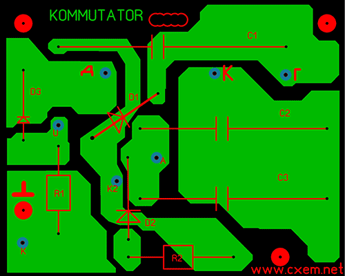
Explanations for the markup:
K – cathode of thyristor KU201
U – controlled electrode of thyristor KU201
A – anode of thyristor Ku202
K2 – cathode of diode D4
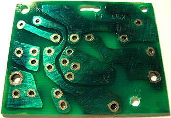
The finished printed circuit board must be coated with a protective varnish to prevent oxidation of the tracks.
Required components:
- 2 zener diodes D817V
- thyristor KU201V
- 3 diodes KD105V
- 2 capacitors 1uF 160V
- 1 capacitor 1uF 250V
- 1K resistor
- resistor 100
The device is assembled in a standard aluminum switch case.
When installing the switch cover, it is necessary to coat all joint seams with sealants to prevent moisture from getting inside.

List of radioelements
| Designation | Type | Denomination | Quantity | Note | Shop | My notepad |
|---|---|---|---|---|---|---|
| T1 | Thyristor & Triac | KU201I | 1 | To notepad | ||
| D1-D3 | Diode | KD105B | 3 | To notepad | ||
| D4, D5 | Zener diode | D817V | 2 | To notepad | ||
| C1 | 1 µF 250 V | 1 | To notepad | |||
| C2, C3 | Electrolytic capacitor | 1 µF 160 V | 2 | To notepad | ||
| R1 | Resistor | 1 kOhm | 1 | 0.5 W | To notepad | |
| R2 | Resistor | 100 Ohm | 1 | 2 W | To notepad | |
| L1 | Ignition winding | 1 | To notepad | |||
| L2 | Sensor | 1 |