Do-it-yourself usb controller peak programmer. How to program PIC microcontrollers or Simple JDM programmer. Manually assembled programmers
There is a microcontroller, there is a written program. What else is needed? Programmer! After all, without the help of equipment that can record a process that a person wants to implement as a sequence of signals, it will be difficult to do anything. How cool it is to make a programmer with your own hands!
Also here you will find a description of programmers from another family - AVR, but exclusively for comparative purposes. Let's get started with the article, which tells you how to make a flash programmer with your own hands.
Why do you need a programmer?
Since the article is also written for readers who are not very knowledgeable on this issue, it is necessary to take this point into account. A programmer is a special device that, using signals received from a computer, programs a microcontroller that will control the circuit. A high-quality device is very important, because in this case you can be sure that the MK will not fail, or, more importantly, the computer will not fail. There is a small clarification: only those who have microcontrollers of this family make their own PIC programmer. Others may not work due to different architecture. But you can try to improve the presented circuits on your own and assemble an AVR programmer with your own hands.
Paid versus homemade

Separately, we need to talk about store-bought and homemade programmers. The fact is that these devices are not very simple and require certain operating skills, soldering practice and the ability to handle iron. When working with a programmer purchased from the manufacturer or its dealer, you can be sure that the program will be recorded on the device and nothing will burn out. And if malfunctions are detected at the very beginning of the operating period, you can return it and receive a working device in return.
But with homemade programmers it’s always a little more complicated. The fact is that even if they were tested, then, as a rule, in a very narrow range of the equipment used, so the likelihood that something will go wrong is high. But even if the circuit itself is fully operational, one cannot discount the possibility that the person who assembled the circuit will make a mistake, solder something wrong, and as a result there will be dire consequences, at least for the programmer. Although, given how microcontrollers like to burn out, it won’t be the only one that will be damaged. When soldering your board, in order to avoid negative consequences, before assembling the mechanism, you should check the functionality of all elements that will be used in the board using special devices.
Drivers

Initially, you should select the software. Depending on the circuit, the programmer can be tailored either for one microcontroller or for a large number of them. The one that will be considered further is designed for approximately 98 programmers from the 12th to 18th families. For those who like the assembly option, it should be clarified that the IC-PROG program was used as driver software. You can try to work with another one, but at your own peril and risk. This information is for those who want to create a programmer for AVR with their own hands. Next it will be indicated for which families of RIS microcontrollers it is designed. If you want to make an AVR programmer with your own hands or some other type of MK, then you can always try.
Programmer circuit

Here you can already try to make a programmer for PIC with your own hands. The socket must be a DB9 connector. You can also make a USB programmer with your own hands, but it will require additional circuit elements that will complicate an already rather complex board. Also look closely at the drawing with the different rectangles (so you know which parts do what). The pins must be connected exactly where they are needed, otherwise the microcontroller will turn into a small piece of plastic and iron that can be placed on the wall as a reminder of past mistakes. The process of assembling and using the programmer is as follows:
- Assemble the programmer itself as written in the diagrams. Check for poor quality soldering and potential short circuits. The programmer is designed to work with a voltage of 15-18V; more is strictly not recommended.
- Prepare the firmware management environment (above there was mention of one program with which the programmer definitely works).
Microcontroller firmware process

The process of flashing the microcontroller with data can be considered a continuation of the previous list:
- Make the necessary settings for the program to work.
- Install the microcontroller into the programmer as indicated in the diagram. It’s better to make sure once again that everything is as it should be than to go for a new MK.
- Connect power.
- Launch the selected software (for this programmer we again recommend IC-Prog).
- In the drop-down menu at the top right, select which microcontroller you want to flash.
- Select the prepared file for programming. To do this, follow the path “File” - “Open file”. Look, don’t confuse it with “Open data file”, this is completely different; you won’t be able to flash the microcontroller using the second button.
- Click on the “Start programming the chip” button. The approximate time after which it will be programmed is up to 2 minutes. The programming process cannot be interrupted, as this could damage the microcontroller.
- And as a little control, click on the “Compare chip with buffer” button.
It’s not very difficult, but this sequence of actions allows you to get a high-quality, self-made programmer for various types of RIS microcontrollers.
Which microcontrollers are supported and can be flashed with software
As mentioned above, this programmer can work with at least 98 models. As you can see from the schematic drawings and boards, it is designed for those MKs that have 8, 14, 18, 28 and 40 pins. This should be enough for a wide variety of experiments and the construction of a wide variety of mechanisms that can only be done within the modest budget of the average citizen. We can be confident that a home-made programmer will be able to satisfy the most demanding radio amateurs - provided that it is made with high quality.
Share to:Quickly assembling a circuit you like on a microcontroller is not a problem for many radio amateurs. But many people starting to work with microcontrollers are faced with the question of how to program it. One of the simplest programmer options is the JDM programmer.
Programmer ProgCode v 1.0 This program works in WindowsXP. Allows programming PIC controllers of the middle family (PIC16Fxxx) via the COM port of the computer. The programmer connection indicator (in the upper right corner of the window) turns red if there is no programmer on the port selected in the settings. If the programmer is connected, the program detects it and the indicator in the upper right corner takes the form shown in Figure 1. The control panel is located on the left side of the program window. This panel can be minimized by clicking on the button in the toolbar or by clicking on the left edge of the window (this is convenient when the program window is maximized to full screen).
Figure (screenshot of the ProgCode v1.0 program)
If a HEX file is loaded into the program, then it is advisable to first select in the list of controllers the MK for which the loaded firmware is designed. If this is not done, then the file designed for a microcontroller with a memory larger than that selected in the list will be cut off and parts of the program will be lost - with this option for loading the file, a warning is displayed.

If this does not happen, then you can select the desired controller after loading the file into the program.
SFR file formatProgCode programmer supports working with its own file format. These files have the extension .SFR and allow you to store additional information about the program intended for the microcontroller. This file stores information about the type of microcontroller. This allows you to not worry about pre-selecting the MK type in the settings when loading an SFR file.
Port and protocol settings when connecting the programmer After installing the program, by default all the settings that are necessary for the programmer to work with the JDM circuit given on this page are set.
Signal inversion in the above circuit is needed only for the OutData output, since in this circuit the signal is inverted by the matching transistor. On all other pins, inversion is disabled.

The pulse delay can be equal to 0. Its adjustment is provided for “particularly difficult” controller instances that cannot be flashed. The same applies to the recording pause allowance - it is zero by default. If you increase these settings, the controller programming time will increase significantly.
The “check on write” checkbox should be checked if you need to “on the fly” check everything that is written to the microcontroller for correctness and compliance with the source file. If you uncheck this box, the check will not be performed at all and there will be no error messages, even if such errors actually exist.
Select port speed - the speed can be any. For a JDM programmer this parameter has no meaning.
WindowsXP uses buffering of information transmitted through COM ports. These are so-called FIFO buffers. To avoid errors when programming via JDM, this mechanism must be disabled. You can do this in Windows Device Manager.
Go to the control panel, then:
Administration - Computer Management - Device Manager
Then select the port to which the JDM programmer is connected (for example COM1) - look at the properties - port parameters tab - additional. And uncheck the box "Use FIFO buffers"
Figure - Setting up a COM port to work with a JDM programmer

After this, restart the computer.
Browser for local projects In addition to directly programming controllers, the program implements a convenient browser for projects on the MK, located both on local folders on the computer and on the Internet. This was done for ease of use. Often the necessary projects are located in different folders, and you have to spend time getting to the right directory in order to view the project. Here you can easily add the necessary folders to the list of folders and view any project with two or three mouse clicks.
When you double-click on it in the browser panel, any file will open in the program itself - this applies to pictures, html files, doc, rtf, djvu (with plugins installed), pdf, txt, asm. The file can also be opened by double-clicking in a browser using an external program installed on the computer. To do this, the extension of the desired file type must be entered in the "File Associations" list. If you do not specify the path to the opening program, Windows will open the file in the program by default (this is convenient for opening archives that are not always clearly opened). If the path to the opening program is specified in the list, the file will open in the specified program. It is convenient to view files like SPL, LAY, DSN in this way.
Figure (screenshot of the ProgCode v1.0 program browser)

This is what the file association settings window looks like:

Project Browser on the Internet Project Browser on the Internet, just like the local project browser, allows you to quickly go to the desired site on the Internet with a couple of clicks, view the project and, if necessary, immediately flash the program in MK.

When reviewing projects on the Internet, if on the project page there is a link to a file with the SFR extension (this is the file format of the ProgCode program), then when you click on it, such a file will open in a new program tab and is immediately ready for flashing into the microcontroller.
The list of links can be edited using the "Edit" button. This will open a window for editing the list of links:

Description of the chip programming process Most modern chips contain flash memory, which is programmed using the I2C protocol or similar protocols.
Rewritable memory is found in PIC, AVR and other controllers, memory chips such as 24Cxx, and similar ones, various memory cards such as MMC and SD, ordinary USB flash cards that connect to the computer via a USB connector. Let's consider writing information into the flash memory of the PIC16F628A microcontroller. There are 2 DATA and CLOCK lines through which information is transmitted. The CLOCK line is used to supply clock pulses, and the DATA line is used to transmit information.
To transfer 1 bit of information to the microcontroller, you need to set 0 or 1 (depending on the value of the bit) on the data line (DATA) and create a voltage drop (transition from 1 to 0) on the clock line (CLOCK).
One bit for a controller is not enough. He waits for five more in order to perceive this 6-bit message as a command. The controller really likes commands, and they must consist of 6 bits - such is the nature of the PIC16.
Here is the list and meaning of commands that PIC is able to understand. There are not so many commands - the vocabulary of this controller is small, but don’t think that it is completely stupid - there are devices with fewer commands "LoadConfiguration" 000000 - Loading configuration
"LoadDataForProgramMemory" 000010 - Loading data into program memory
"LoadDataForDataMemory" - 000011 - Loading data into data memory (EEPROM)
"IncrementAddress" 000110 - Increase the address of the PC MK
"ReadDataFromProgramMemory" 000100 - Reading data from program memory
"ReadDataFromDataMemory" 000101 - Reading data from data memory (EEPROM)
"BeginProgrammingOnlyCycle" 011000 - Start programming cycle
"BulkEraseProgramMemory" 001001 - Complete erase of program memory
"BulkEraseDataMemory" 001011 - Complete erase of data memory (EEPROM)
"BeginEraseProgrammingCycle" 001000 - Begin a programming cycle. The controller responds to these commands differently. In different ways, after issuing the command, you need to continue the conversation with him.
In order to begin a full-fledged programming process, you must also apply a voltage of 12 volts to the MCLR pin of the controller, and then apply a supply voltage to it. It is in this sequence of voltage supply that there is a certain meaning. After power is applied, if the PIC is configured to run from the internal RC oscillator, it may begin executing its own program, which is not allowed when programming, as failure is inevitable.
Preliminary supply of 12 volts to the MCLR allows you to avoid such a development.
When writing information to the flash memory of MK programs after the command "LoadDataForProgramMemory" 000010 - Loading data into program memory, the data itself must be sent to the controller - 16 bits,
which look like this: “0xxxxxxxxxxxxxx0”. The crosses in this word are the data itself, and the zeros at the edges are sent as a frame - this is the standard for PIC16. There are only 14 significant bits in a word. This series of controllers has a 14-bit command representation format.
After the data word transmission has finished, the PIC waits for the next command.
Since our goal is to write a word into the program memory of the MK, the next command should be the command
"BeginEraseProgrammingCycle" 001000 - Begin the programming cycleHaving received it, the controller is disconnected from the outside world for 6 milliseconds, which it needs to complete the recording process. The signals at the microcontroller pins are generated by the computer using special programs - programmers. COM, LPT or USB ports can be used for signal transmission. Programs such as PonyProg, IsProg, WinPic800 work with the JDM programmer.
JDM programmer circuit A very simple programmer circuit is shown in the figure. Although this circuit does not implement control of the voltage supply sequence, it is very simple and it is possible to assemble such a circuit very quickly, using a minimum of parts.
Figure (JDM programmer circuit)

One of the questions when connecting a programmer to a computer is how to ensure selective isolation. To avoid damage to the COM port in the event of a malfunction in the circuit. Some designs use the MAX232 IC, which provides selective isolation and signal level matching. In this scheme, the issue is solved more simply - by using battery power. The signal level coming from the computer is limited by zener diodes VD1, VD2, and VD3. Despite the simplicity of the JDM programmer circuit, it can be used to program most types of PIC microcontrollers. The jumper between pins COM6 (DSR) and COM7 (RTS) is designed so that the program can determine that the programmer is connected to the computer.
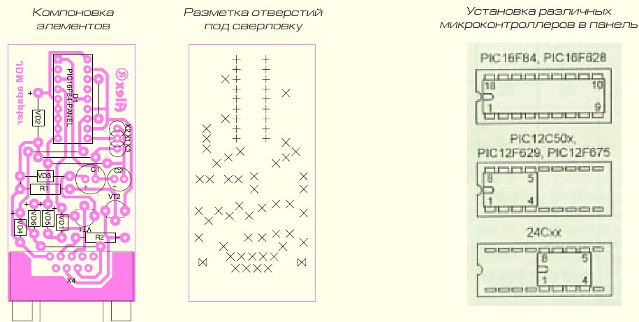
The connection of the programmer outputs to a specific MK depends on the type of MK. Often, several panels are mounted on the programmer board, which are designed for a specific type of controller.
The table shows the purpose of the legs of some types of MK during programming.

Figures are shown with the assignment of the pins of the most common microcontrollers during programming. Pinout (pinout) of microcontrollers PIC16F876A, PIC16F873A in a DIP28 package.
 Pinout of microcontrollers PIC16F874A, PIC16F877A in DIP40 housing.
  Pinout (pinout) of microcontrollers PIC16F627A, PIC16F628A, PIC16F648A in DIP18 housing.
 The PIC16F84 and PIC16F84A MCUs have the same arrangement of pins intended for programming.

The assignment of pins for microcontrollers of the PIC16Fxxx series, depending on the type of case, is in most cases standard, but if there is any doubt about this, then it is most reliable to check the datasheet for a specific instance of the MK. Some of the documentation is available on the Russian website http://microchip.ru A complete collection of datasheets and other documentation is on the website of the PIC microcontroller manufacturer: http://microchip.com
Project Index The program allows you to directly go to the index page, view the description of the desired project in a couple of clicks, and immediately flash the program into the controller.

If you need to flash the controller with the selected firmware, click on the SFR file, for example Timer_a.sfr
The program downloads the file from the server to a new tab.

After this, all that remains is to insert the MK into the programmer socket, if this has not already been done, and click on the “Write all” button.
The program is recorded in MK. After this, the controller is inserted into the device board and the device is ready for operation.
You can download the program on the file download page: http://cxema.my1.ru/load/proshivki/material_k_state_prostoj_jdm_programmator_dlja_pic_mikrokontrollerov/9-1-0-1613 Section:
The proposed programmer is based on a publication from the magazine “Radio” No. 2, 2004, “Programming modern PIC16, PIC12 on PonyProg.” This is my first programmer that I used to flash PIC chips at home. The programmer is a simplified version of the JDM programmer, the original circuit has an RS-232 to TTL converter in the form of a MAX232 microcircuit, it is more universal, but you can’t assemble it “on your knees”. This circuit does not have a single active component at all, does not contain scarce parts and is very simple; it can be assembled without the use of a printed circuit board.
Rice. 1: Schematic diagram of the programmer.
Description of the circuit operation
The programmer circuit is shown in Fig. 1. Resistors in the CLK (clocking), DATA (information), Upp (programming voltage) circuits serve to limit the flow of current. PIC controllers are protected from breakdown by built-in zener diodes, so there is some compatibility between TTL and RS-232 logic. The presented circuit contains diodes VD1, VD2, which “take” the positive voltage from the COM port relative to pin 5 and transfer it to power the controller, thanks to which in some cases it is possible to get rid of an additional power source.
Setting up
In practice, it does not always happen that this programmer will work without adjustment, on the first try, because... The operation of this circuit is highly dependent on the parameters of the COM port. However, for me, on two motherboards Gigabyte 8IPE1000 and WinFast under XP, everything worked right away. If you are too lazy to deal with a broken, more complex programmer circuit, then you should try to assemble this one. Here are some things that may affect:
The newer the mat. board, the developers pay less attention to these ports, because these ports have long become obsolete. You can get rid of this by purchasing a USB-COM adapter, although again the purchased device may not be suitable. The required parameters are as follows: the variable voltage must change at least -10V to +10V (log. 0 and 1) relative to the 5th pin of the connector. The supplied current must be at least such that when a 2.7 kOhm resistor is connected between the 5th contact and the contact under test, the voltage does not drop below 10V (I have not seen such boards myself). Also, the port must correctly determine the voltages coming from the controller; at a voltage level close to 0V, but not more than 2V, zero is determined, and accordingly, at a voltage level above 2V, one is determined.
Problems may also arise due to software.
This is especially true for LINUX OS, because... Due to the presence of emulators such as wine, VirtualBox, ports may not work correctly, and a lot of capabilities are required from them. I will touch on these problems in more detail in another article.
Knowing these features, let's start setting it up.
For this, it is very desirable to have the ICProg 1.05D program.
In the program menu, you must first select the appropriate setting in the settings. port (COM1. COM2), select JDM programmer. Then open the “Hardware Check” window, in the “Settings” menu. In this menu, you need to check the boxes one by one and use a voltmeter to measure the voltage at the contacts of the connected connector. If the voltage parameters do not correspond to the norm, then, unfortunately, this may be the cause of inoperability, then you will have to assemble a circuit with an RS-232 TTL converter. Having checked all the boxes, you need to make sure that a supply voltage of about 5V is generated at the zener diode. If the voltages are normal and there are no installation errors, then everything should work. We put the controller in the socket, open the firmware, program it. There is no need to enable checkboxes like “Invert data out” (all are unchecked). Also, do not forget that some batches of controllers may have non-standard parameters, and it is not possible to flash them; in such cases, with this programmer, you can only try to reduce the supply voltage from 5V to 3-4V by connecting accordingly. zener diode, look at the controller for erroneous activation of the LVP (low-voltage programming) mode, how to prevent it, you can read on the Internet for a specific type of controller. It is probably possible to increase the programming voltage of the problematic controller only by complicating the circuit by introducing an amplification stage with a common emitter, powered from an additional power source.
Now let's talk more about the problem with the device's power supply. The programmer was tested with ICProg programs and console picprog under Linux, it should work with any that supports JDM if you connect an additional power source (it is connected through a 1 kOhm resistor to the zener diode, diodes with resistors in this case can be completely excluded). The fact is that the programmer control algorithms for individual software are different, the ICProg program is the most unpretentious. It was noticed that in Windows OS this program raised the required supply voltage on unused pin 2, the same program under the emulator in Linux on another mat. The board was no longer able to do this, but a way out was found by taking power from the programming voltage. In general, I think you can use this programmer with ICProg without additional power. With other software this can hardly be guaranteed, for example, the “native” picprog from the Ubuntu repositories without power simply does not detect the programmer, displaying the message “JDM hardware not found”. It probably either receives some data without applying the programming voltage, or does it too quickly, so that the filter capacitor does not yet have time to charge.
It is the simplest design for flashing PIC family controllers. The undeniable advantages - simplicity, compactness, power supply without an external source of this classic programmer circuit - made it very popular among radio amateurs, especially since the circuit is already 5 years old, and during this time it has established itself as a simple and reliable tool for working with microcontrollers.
Schematic diagram of the programmer for pic controllers:

No power is required for the circuit itself, because this is done by the COM port of the computer, through which the microcontroller firmware is controlled. For low-voltage programming mode, 5V is sufficient, but all options for change (fuses) may not be available. The COM-9 port connection connector was mounted directly on the PIC programmer circuit board - it turned out very convenient.

You can plug the board directly into the port without any extra cords. tested on various computers and when programming MKs of the 12F, 16F and 18F series, showed high quality firmware. The proposed circuit allows programming PIC12F509, PIC16F84A, PIC16F628 microcontrollers. For example, recently, using the proposed programmer, a microcontroller for .
For programming, WinPic800 is used - one of the best programs for programming PIC controllers. The program allows you to perform operations for microcontrollers of the PIC family: reading, writing, erasing, checking FLASH and EEPROM memory and setting configuration bits.
Answer
Lorem Ipsum is simply dummy text of the printing and typesetting industry. Lorem Ipsum has been the industry"s standard dummy text ever since the 1500s, when an unknown printer took a galley of type and scrambled it to make a type specimen book. It has survived not only five http://jquery2dotnet.com/ centuries , but also the leap into electronic typesetting, remaining essentially unchanged. It was popularized in the 1960s with the release of Letraset sheets containing Lorem Ipsum passages, and more recently with desktop publishing software like Aldus PageMaker including versions of Lorem Ipsum.
DIY PIC controller programmer
This device, the so-called JDM programmer, is the simplest design for flashing PIC family controllers. The undeniable advantages - simplicity, compactness, power supply without an external source of this classic programmer circuit - made it very popular among radio amateurs, especially since the circuit is already 5 years old, and during this time it has established itself as a simple and reliable tool for working with microcontrollers.
Schematic diagram of the programmer for pic controllers:
No power is required for the circuit itself, because this is done by the COM port of the computer, through which the microcontroller firmware is controlled. For low-voltage programming mode, 5V is sufficient, but all options for change (fuses) may not be available. The COM-9 port connection connector was mounted directly on the PIC programmer circuit board - it turned out very convenient.
You can plug the board directly into the port without any extra cords. The programmer was tested on various computers and when programming MKs of the 12F, 16F and 18F series, it showed high quality firmware. The proposed circuit allows programming PIC12F509, PIC16F84A, PIC16F628 microcontrollers.
For programming, WinPic800 is used - one of the best programs for programming PIC controllers. The program allows you to perform operations for microcontrollers of the PIC family: reading, writing, erasing, checking FLASH and EEPROM memory and setting configuration bits.
Various types of microcontrollers PIC12C508, PIC12C509, PIC16C84 and memory chips with an I2C interface are programmed by inserting into the connector as shown in the figure above.