Thermistors and their use in cars. The working principle of a thermistor. On electrical diagrams, thermistors are designated
The word “thermistor” is self-explanatory: THERMAL RESISTOR is a device whose resistance changes with temperature.
Thermistors are largely nonlinear devices and often have large variations in parameters. This is why many, even experienced engineers and circuit designers, experience inconvenience when working with these devices. However, having taken a closer look at these devices, you can see that thermistors are actually quite simple devices.
First, it must be said that not all devices that change resistance with temperature are called thermistors. For example, resistive thermometers, which are made from small coils of twisted wire or from sputtered metal films. Although their parameters depend on temperature, however, they work differently from thermistors. Typically, the term "thermistor" is applied to temperature-sensitive semiconductor devices.
There are two main classes of thermistors: negative TCR (temperature coefficient of resistance) and positive TCR.
There are two fundamentally different types of manufactured thermistors with positive TCR. Some are made like NTC thermistors, while others are made from silicon. Positive TCR thermistors will be described briefly, with the focus on the more common negative TCR thermistors. Thus, unless there are special instructions, we will be talking about thermistors with negative TCR.
NTC thermistors are highly sensitive, narrow range, nonlinear devices whose resistance decreases as temperature increases. Figure 1 shows a curve showing the change in resistance depending on temperature and is a typical temperature dependence of resistance. Sensitivity is approximately 4-5%/o C. There is a wide range of resistance values, and the change in resistance can reach many ohms and even kilo-ohms per degree.
R R oFig.1 Negative TCR thermistors are very sensitive and significantly
The degrees are non-linear. R o can be in ohms, kilo-ohms or mego-ohms:
1-resistance ratio R/R o; 2- temperature in o C
Thermistors are essentially semiconductor ceramics. They are made from metal oxide powders (usually nickel and manganese oxides), sometimes with the addition of small amounts of other oxides. Powdered oxides are mixed with water and various binders to obtain a liquid dough, which is given the required shape and fired at temperatures above 1000 o C.A conductive metal covering (usually silver) is welded on and the leads are connected. The completed thermistor is usually coated with epoxy resin or glass, or enclosed in some other housing.
From Fig. 2 you can see that there are many types of thermistors.
Thermistors have the form of disks and washers with a diameter of 2.5 to approximately 25.5 mm, and the shape of rods of various sizes.
Some thermistors are first made as large plates and then cut into squares. Very small bead thermistors are made by directly burning a drop of dough onto two refractory titanium alloy terminals and then dipping the thermistor into glass to create a coating.
Typical parameters
To say “typical parameters” is not entirely correct, since there are only a few typical parameters for thermistors. There are an equally large number of specifications available for a variety of thermistor types, sizes, shapes, ratings, and tolerances. Moreover, often thermistors produced by different manufacturers are not interchangeable.
You can purchase thermistors with resistances (at 25 o C - the temperature at which the thermistor resistance is usually determined) from one ohm to ten megohms or more. Resistance depends on the size and shape of the thermistor, however, for each specific type, resistance ratings can differ by 5-6 orders of magnitude, which is achieved by simply changing the oxide mixture. When replacing the mixture, the type of temperature dependence of the resistance (R-T curve) also changes and the stability at high temperatures changes. Fortunately, thermistors with high resistance enough to be used at high temperatures also tend to be more stable.Inexpensive thermistors usually have fairly large parameter tolerances. For example, permissible resistance values at 25 o C vary in the range from ± 20% to ± 5%. At higher or lower temperatures, the spread of parameters increases even more. For a typical thermistor having a sensitivity of 4% per degree Celsius, the corresponding measured temperature tolerances range from approximately ±5°C to ±1.25°C at 25°C. High precision thermistors will be discussed later in this article.
It was previously said that thermistors are narrow range devices. This needs to be explained: most thermistors operate in the range from -80°C to 150°C, and there are devices (usually glass-coated) that operate at 400°C and higher temperatures. However, for practical purposes, the greater sensitivity of thermistors limits their useful temperature range. The resistance of a typical thermistor can vary by a factor of 10,000 or 20,000 at temperatures ranging from -80°C to +150°C. One can imagine the difficulty in designing a circuit that provides accurate measurements at both ends of this range (unless range switching is used). Thermistor resistance, rated at zero degrees, will not exceed several ohms at
Most thermistors use soldering to connect the leads internally. Obviously, such a thermistor cannot be used to measure temperatures above the melting point of solder. Even without soldering, the epoxy coating of thermistors only lasts at a temperature of no more than 200 ° C. For higher temperatures, it is necessary to use glass-coated thermistors with welded or fused leads.
Stability requirements also limit the use of thermistors at high temperatures. The structure of thermistors begins to change when exposed to high temperatures, and the rate and nature of the change is largely determined by the oxide mixture and the method of manufacturing the thermistor. Some drift in epoxy coated thermistors begins at temperatures above 100°C or so. If such a thermistor operates continuously at 150 o C, then the drift can be measured by several degrees per year. Low-resistance thermistors (for example, no more than 1000 ohms at 25 o C) are often even worse - their drift can be noticed when operating at approximately 70 o C. And at 100 o C they become unreliable.
Inexpensive devices with larger tolerances are manufactured with less attention to detail and can produce even worse results. On the other hand, some properly designed glass-coated thermistors have excellent stability even at higher temperatures. Glass-coated bead thermistors have very good stability, as do the more recently introduced glass-coated disk thermistors. It should be remembered that drift depends on both temperature and time. For example, it is usually possible to use an epoxy coated thermistor when briefly heated to 150°C without significant drift.
When using thermistors, the nominal value must be taken into account constant power dissipation. For example, a small epoxy-coated thermistor has a dissipation constant of one milliwatt per degree Celsius in still air. In other words, one milliwatt of power in a thermistor increases its internal temperature by one degree Celsius, and two milliwatts increases its internal temperature by two degrees, and so on. If you apply a voltage of one volt to a one-kilo-ohm thermistor that has a dissipation constant of one milliwatt per degree Celsius, you will get a measurement error of one degree Celsius. Thermistors dissipate more power if they are lowered into liquid. The same small epoxy coated thermistor mentioned above dissipates 8 mW/°C when placed in well-mixed oil. Larger thermistors have better consistent dissipation than smaller devices. For example, a thermistor in the form of a disk or washer can dissipate a power of 20 or 30 mW/o C in air; it should be remembered that, just as the resistance of a thermistor changes depending on temperature, its dissipated power also changes.
Equations for thermistors
There is no exact equation to describe the behavior of a thermistor; there are only approximate ones. Let's consider two widely used approximate equations.
The first approximate equation, exponential, is quite satisfactory for limited temperature ranges, especially when using thermistors with low accuracy.
Often in various power supplies the task arises of limiting the starting current surge when turned on. The reasons may be different - rapid wear of relay contacts or switches, reduced service life of filter capacitors, etc. I recently had a similar problem. I use a good server power supply in my computer, but due to the unsuccessful implementation of the standby section, it overheats severely when the main power is turned off. Because of this problem, I had to repair the standby board twice already and change some of the electrolytes located next to it. The solution was simple - turn off the power supply from the outlet. But it had a number of disadvantages - when turned on, there was a strong surge of current through the high-voltage capacitor, which could damage it, in addition, after 2 weeks the power plug of the unit began to burn out. It was decided to make an inrush current limiter. In parallel with this task, I had a similar task for powerful audio amplifiers. The problems in amplifiers are the same - burning of switch contacts, current surge through the bridge diodes and filter electrolytes. You can find quite a lot of surge current limiter circuits on the Internet. But for a specific task, they may have a number of disadvantages - the need to recalculate circuit elements for the required current; for powerful consumers - selection of power elements that provide the necessary parameters for the calculated allocated power. In addition, sometimes it is necessary to provide a minimum starting current for the connected device, which increases the complexity of such a circuit. To solve this problem, there is a simple and reliable solution - thermistors.
Fig.1 Thermistor
A thermistor is a semiconductor resistor whose resistance changes sharply when heated. For our purposes, we need thermistors with a negative temperature coefficient - NTC thermistors. When current flows through the NTC thermistor, it heats up and its resistance drops.
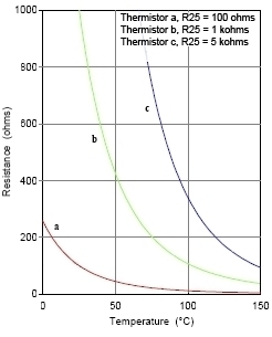
Fig.2 TKS thermistor
We are interested in the following thermistor parameters:
Resistance at 25˚C
Maximum steady current
Both parameters are in the documentation for specific thermistors. Using the first parameter, we can determine the minimum current that will pass through the load resistance when connecting it through a thermistor. The second parameter is determined by the maximum power dissipation of the thermistor and the load power must be such that the average current through the thermistor does not exceed this value. For reliable operation of the thermistor, you need to take the value of this current less than 20 percent of the parameter specified in the documentation. It would seem that it would be easier to select the right thermistor and assemble the device. But you need to consider some points:
- The thermistor takes a long time to cool down. If you turn off the device and immediately turn it on again, the thermistor will have low resistance and will not perform its protective function.
- You cannot connect thermistors in parallel to increase the current - due to the spread of parameters, the current through them will vary greatly. But it is quite possible to connect the required number of thermistors in series.
- During operation, the thermistor becomes very hot. The elements next to it also heat up.
- The maximum steady-state current through the thermistor should be limited by its maximum power. This option is listed in the documentation. But if the thermistor is used to limit short current surges (for example, when the power supply is initially turned on and the filter capacitor is charging), then the pulse current may be greater. Then the choice of thermistor is limited by its maximum pulse power.
The energy of a charged capacitor is determined by the formula:
E = (C*Vpeak²)/2
where E is the energy in joules, C is the capacitance of the filter capacitor, Vpeak is the maximum voltage to which the filter capacitor will be charged (for our networks you can take the value 250V*√2 = 353V).
If the documentation indicates the maximum pulse power, then based on this parameter you can select a thermistor. But, as a rule, this parameter is not specified. Then the maximum capacity that can be safely charged with a thermistor can be estimated from the already calculated tables for thermistors of standard series.
I took a table with the parameters of NTC thermistors from Joyin. The table shows:
Rnom- nominal resistance of the thermistor at a temperature of 25°C
Imax- maximum current through the thermistor (maximum steady-state current)
Smax- maximum capacity in the test circuit that is discharged onto the thermistor without damaging it (test voltage 350v)
You can see how the test is carried out on page seven.
A few words about the parameter Smax– the documentation shows that in the test circuit the capacitor is discharged through a thermistor and a limiting resistor, which releases additional energy. Therefore, the maximum safe capacity that a thermistor can charge without such resistance will be less. I searched for information in foreign thematic forums and looked at typical circuits with limiters in the form of thermistors, for which data is given. Based on this information, you can take the coefficient for Smax in a real scheme 0.65, by which to multiply the data from the table.
|
Name |
Rnom, |
Imax, |
Smax, |
|
|
ddiameter 8mm |
||||
|
diameter 10mm |
||||
|
diameter 13mm |
||||
|
diameter 15mm |
||||
|
diameter 20mm |
||||
Table of parameters of NTC thermistors from Joyin
By connecting several identical NTC thermistors in series, we reduce the requirements for the maximum pulse energy of each of them.
Let me give you an example. For example, we need to select a thermistor to turn on the computer power supply. The maximum power consumption of the computer is 700 watts. We want to limit the starting current to 2-2.5A. The power supply contains a 470 µF filter capacitor.
We calculate the effective current value:
I = 700W/220V = 3.18A
As I wrote above, for reliable operation of the thermistor, we will select the maximum steady-state current from the documentation that is 20% greater than this value.
Imax = 3.8A
We calculate the required thermistor resistance for a starting current of 2.5A
R = (220V*√2)/2.5A = 124 Ohm
From the table we find the required thermistors. 6 pieces of JNR15S200L thermistors connected in series suit our needs Imax, general resistance. The maximum capacity that they can charge will be 680 µF * 6 * 0.65 = 2652 µF, which is even more than we need. Naturally, with a decrease Vpeak, the requirements for the maximum pulse power of the thermistor are also reduced. Our dependence is on the square of the voltage.
And the last question about the choice of thermistors. What if we have selected the thermistors required for maximum pulse power, but they are not suitable for us? Imax(the constant load is too high for them), or do we not need a source of constant heating in the device itself? To do this, we will use a simple solution - we will add another switch to the circuit in parallel with the thermistor, which we will turn on after charging the capacitor. Which is what I did in my limiter. In my case, the parameters are as follows: the maximum power consumption of the computer is 400W, the starting current limitation is 3.5A, the filter capacitor is 470uF. I took 6 pieces of 15d11 (15 ohm) thermistors. The diagram is shown below.

Rice. 3 Limiter circuit
Explanations for the diagram. SA1 disconnects the phase wire. LED VD2 serves to indicate the operation of the limiter. Capacitor C1 smoothes out ripples and the LED does not flicker at the mains frequency. If you don’t need it, then remove C1, VD6, VD1 from the circuit and simply connect the LED and diode in parallel in the same way as the elements VD4, VD5. To indicate the charging process of the capacitor, LED VD4 is connected in parallel with the thermistors. In my case, when charging the capacitor of the computer power supply, the entire process takes less than a second. So, let's collect.

Fig.4 Assembly kit
I assembled the power indicator directly in the cover of the switch, throwing out a Chinese incandescent lamp, which would not have lasted long.


Rice. 5 Power indicator

Fig.6 Thermistor block


Rice. 7 Assembled limiter
This could have been completed if all the thermistors had not failed after a week of work. It looked like this.

Rice. 8 Failure of NTC thermistors
Despite the fact that the margin for the permissible capacitance value was very large - 330 µF * 6 * 0.65 = 1287 µF.
I bought the thermistors from a well-known company, with different values - all defective. Manufacturer unknown. Either the Chinese pour thermistors of smaller diameters into large cases, or the quality of the materials is very poor. As a result, I bought an even smaller diameter - SCK 152 8mm. The same China, but already branded. According to our table, the permissible capacitance is 100 µF * 6 * 0.65 = 390 µF, which is even slightly less than needed. However, everything works fine.
Semiconductor resistors whose resistance depends on temperature are called thermistors. They have the property of a significant temperature coefficient of resistance, the value of which is many times greater than that of metals. They are widely used in electrical engineering.
On electrical diagrams, thermistors are designated:

Design and operation
They have a simple design and are available in different sizes and shapes.

Semiconductors contain two types of free charge carriers: electrons and holes. At a constant temperature, these carriers randomly form and disappear. The average number of free carriers is in dynamic equilibrium, that is, unchanged.
When the temperature changes, the equilibrium is disrupted. If the temperature increases, the number of charge carriers also increases, and as the temperature decreases, the carrier concentration decreases. The resistivity of a semiconductor is influenced by temperature.

If the temperature approaches absolute zero, then the semiconductor has the property of a dielectric. When heated strongly, it conducts current perfectly. The main feature of the thermistor is that its resistance most noticeably depends on temperature in the usual temperature range (-50 +100 degrees).
Popular thermistors are manufactured in the form of a semiconductor rod that is coated with enamel. Electrodes and contact caps are connected to it. Such resistors are used in dry places.
Some thermistors are placed in a sealed metal case. Therefore, they can be used in damp places with aggressive external environments.
The tightness of the case is created using tin and glass. The semiconductor rods are wrapped in metallized foil. Nickel wire is used to connect the current. The nominal resistance value is 1-200 kOhm, operating temperature -100 +129 degrees.
The operating principle of a thermistor is based on the property of changing resistance with temperature. Pure metals are used for manufacturing: copper and platinum.
Main settings
- TKS– thermal coefficient of resistance, is equal to the change in resistance of a circuit section when the temperature changes by 1 degree. If the TCS is positive, then thermistors are called posistors(RTS thermistors). And if the TCS is negative, then thermistors(NTS thermistors). For posistors, as the temperature rises, the resistance also increases, but for thermistors the opposite happens.
- Nominal resistance – this is the resistance value at 0 degrees.
- Operating range. Resistors are divided into low-temperature (less than 170K), medium-temperature (from 170 to 510K), high-temperature (more than 570K).
- Power dissipation . This is the amount of power within which the thermistor, during operation, ensures that the specified parameters are maintained according to technical conditions.
Types and features of thermistors
All temperature sensors in production operate on the principle of converting temperature into an electric current signal, which can be transmitted at high speed over long distances. Any quantities can be converted into electrical signals by converting them into digital code. They are transmitted with high accuracy and processed by computer technology.
Metal thermistors
Not all current conductors can be used as material for thermistors, since thermistors have certain requirements. The material for their manufacture must have a high TCR, and the resistance must depend on temperature according to a linear graph over a wide temperature range.
Also, a metal conductor must be inert to the aggressive actions of the external environment and reproduce high-quality characteristics, which makes it possible to change sensors without special settings and measuring instruments.
Copper and platinum are well suited for such requirements, despite their high cost. Thermistors based on them are called platinum and copper. TSP (platinum) thermal resistances operate at temperatures of -260 - 1100 degrees. If the temperature is in the range from 0 to 650 degrees, then such sensors are used as samples and standards, since in this range the instability is no more than 0.001 degrees.
The disadvantages of platinum thermistors include nonlinearity of conversion and high cost. Therefore, accurate measurements of parameters are possible only in the operating range.
Inexpensive copper samples of TCM thermistors are practically widely used, in which the linearity of the dependence of resistance on temperature is much higher. Their disadvantage is low resistivity and instability to elevated temperatures, rapid oxidation. In this regard, copper-based thermal resistances have limited use, no more than 180 degrees.
For installation of platinum and copper sensors, a 2-wire line is used at a distance to the device of up to 200 meters. If the distance is greater, then they are used, in which the third conductor serves to compensate for the resistance of the wires.
Among the disadvantages of platinum and copper thermistors, one can note their low operating speed. Their thermal inertia reaches several minutes. There are thermistors with low inertia, the response time of which is no more than a few tenths of a second. This is achieved by the small size of the sensors. Such thermal resistances are made from microwire in a glass shell. These sensors have low inertia, are sealed and highly stable. Although small in size, they have a resistance of several kOhms.
Semiconductor
Such resistances are called thermistors. If we compare them with platinum and copper samples, they have increased sensitivity and a negative TCR value. This means that as the temperature increases, the resistance of the resistor decreases. Thermistors have much greater TCR than platinum and copper sensors. With small sizes, their resistance reaches 1 megohm, which does not allow the measurement of conductor resistance to be influenced.
For temperature measurements, thermistors based on KMT semiconductors, consisting of cobalt and manganese oxides, as well as MMT thermal resistors based on copper and manganese oxides have become very popular. The dependence of resistance on temperature on the graph has good linearity in the temperature range -100 +200 degrees. The reliability of thermistors based on semiconductors is quite high; their properties are sufficiently stable over a long time.
Their main disadvantage is the fact that during mass production of such thermistors it is not possible to ensure the necessary accuracy of their characteristics. Therefore, one individual resistor will differ from another sample, just like transistors, which from the same batch can have different gain factors, it is difficult to find two identical samples. This negative point creates the need for additional adjustment of the equipment when replacing the thermistor.
To connect thermistors, a bridge circuit is usually used, in which the bridge is balanced by a potentiometer. As the resistance of the resistor changes due to temperature, the bridge can be brought into equilibrium by adjusting the potentiometer.
This manual setup method is used in teaching laboratories to demonstrate operation. The potentiometer regulator is equipped with a scale that is graduated in degrees. In practice, in complex measurement schemes, this adjustment occurs automatically.
Application of thermistors
There are two modes of operation of temperature sensors. In the first mode, the sensor temperature is determined only by the ambient temperature. The current flowing through the resistor is small and is not able to heat it.

In mode 2, the thermistor is heated by the flowing current, and its temperature is determined by the conditions of heat transfer, for example, blowing speed, gas density, etc.

Thermistors on the diagrams (NTS) and resistors (RTS) have respectively negative and positive resistance coefficients, and are designated as follows:

Applications of thermistors
- Temperature measurement.
- Household appliances: freezers, hair dryers, refrigerators, etc.
- Automotive electronics: antifreeze and oil cooling measurement, exhaust gas control, braking systems, interior temperature.
- Air conditioners: heat distribution, room temperature control.
- Door locking in heating devices.
- Electronics industry: temperature stabilization of lasers and diodes, as well as copper coil windings.
- In mobile phones to compensate for heating.
- Limiting the starting current of motors, lighting lamps, .
- Liquid filling control.
Application of posistors
- Protection against in engines.
- Protection against melting during current overload.
- To delay the turn-on time of switching power supplies.
- Computer monitors and TV picture tubes for degaussing and preventing color distortion.
- In refrigerator compressor starters.
- Thermal blocking of transformers and motors.
- Information memory devices.
- As carburetor heaters.
- In household devices: closing the door of a washing machine, in hair dryers, etc.
1. WHAT IS THIS?
A thermistor is a semiconductor resistor that uses the temperature dependence of the semiconductor resistance.
Thermistors are characterized by a large temperature coefficient of resistance (TCR), the value of which exceeds that of metals by tens and even hundreds of times.
Thermistors are designed very simply and are manufactured in various shapes and sizes 
In order to more or less imagine the physical basis of the operation of this radio component, you should first become familiar with the structure and properties of semiconductors (see my article “Semiconductor Diode”).
A quick reminder. Semiconductors contain two types of free electric charge carriers: “-” electrons and “+” holes. At a constant ambient temperature, they spontaneously form (dissociation) and disappear (recombination). Average concentration of free carriers in a semiconductor  remains unchanged - this is a dynamic equilibrium. When the temperature changes, this equilibrium is disrupted: if the temperature increases, then the concentration of carriers increases (conductivity increases, resistance decreases), and if it decreases, then the concentration of free carriers also decreases (conductivity decreases, resistance increases).
The dependence of the resistivity of a semiconductor on temperature is shown in the graph.
As you can see, if the temperature tends to absolute zero (-273.2C), then the semiconductor becomes an almost ideal dielectric. If the temperature increases greatly, then, on the contrary, it becomes an almost ideal conductor. But the most important thing is that the R(T) dependence of a semiconductor is strongly expressed in the range of ordinary temperatures, say, from -50C to +100C (you can take it a little wider).
 The thermistor was invented by Samuel Reuben in 1930.
2. MAIN PARAMETERS
2.1. Nominal resistance - resistance of the thermistor at 0°C (273.2K)
2.2. TKS is physical a value equal to the relative change in the electrical resistance of a section of an electrical circuit or the resistivity of a substance when the temperature changes by 1°C (1K).
There are thermistors with negative ( thermistors) and positive ( posistors) TKS. They are also called NTC thermistors (Negative temperature coefficient) and PTC thermistors (Positive temperature coefficient), respectively. For posistors, as the temperature increases, the resistance also increases, but for thermistors, the opposite is true: as the temperature increases, the resistance decreases.
The TCS value is usually given in reference books for a temperature of 20°C (293 K).
2.3. Operating temperature range
There are low-temperature thermistors (designed to operate at temperatures below 170 K), medium-temperature (170–510 K) and high-temperature (above 570 K). In addition, there are thermistors designed to operate at 4.2 K and below and at 900–1300 K. The most widely used are medium temperature thermistors with a TCR of -2.4 to -8.4%/K and a nominal resistance of 1–106 ohms .
 Note. In physics, the so-called absolute temperature scale (thermodynamic scale) is used. According to it, the lowest temperature in nature (absolute zero) is taken as the starting point. On this scale, the temperature can only be with a “+” sign. There is no negative absolute temperature. Designation: T, unit of measure 1K (Kelvin). 1K=1°C, therefore the formula for converting temperature from the Celsius scale to the thermodynamic temperature scale is very simple: T=t+273 (approximately) or, accordingly, vice versa: t=T-273. Here t is the temperature on the Celsius scale.
The relationship between the Celsius and Kelvin scales is shown in
2.4. Rated power dissipation is the power at which the thermistor maintains its parameters within the limits specified by the technical specifications during operation.
3. OPERATING MODE  The operating mode of thermistors depends on which part of the static current-voltage characteristic (volt-ampere characteristic) the operating point is selected. In turn, the current-voltage characteristic depends both on the design, dimensions and main parameters of the thermistor, and on temperature, thermal conductivity of the environment, and the thermal connection between the thermistor and the environment. Thermistors with an operating point at the initial (linear) section of the current-voltage characteristic are used to measure and control temperature and compensate for temperature changes in the parameters of electrical circuits and electronic devices. Thermistors with an operating point in the descending section of the current-voltage characteristic (with negative resistance) are used as starting relays, time relays, power meters of electromagnetic radiation in the microwave, temperature and voltage stabilizers. The operating mode of the thermistor, in which the operating point is also on the descending section of the current-voltage characteristic (this uses the dependence of the thermistor resistance on the temperature and thermal conductivity of the environment), is typical for thermistors used in thermal systems.
  control and fire alarm, regulation of the level of liquid and granular media; the action of such thermistors is based on the occurrence of a relay effect in the circuit with the thermistor when the ambient temperature changes or the conditions of heat exchange between the thermistor and the medium.
There are thermistors of a special design - with indirect heating. Such thermistors have a heated winding, isolated from the semiconductor resistive element (if the power released in the resistive element is small, then the thermal regime of the thermistor is determined by the temperature of the heater, and, consequently, the current in it). Thus, it becomes possible to change the state of the thermistor without changing the current through it. Such a thermistor is used as a variable resistor controlled electrically from a distance.
Of the thermistors with a positive temperature coefficient, the most interesting are thermistors made from BaTiO-based solid solutions. They are called posistors. There are known thermistors with a small positive TCR (0.5–0.7%/K), made on the basis of silicon with electronic conductivity; their resistance changes with temperature approximately linearly. Such thermistors are used, for example, for temperature stabilization of electronic devices using transistors.
In Fig. shows the dependence of the thermistor resistance on temperature. Line 1 - for TKS< 0, линия 2 - для ТКС > 0.
4. APPLICATION
When using thermistors as sensors, two main modes are distinguished.
In the first mode, the temperature of the thermistor is practically determined only by the ambient temperature. The current passing through the thermistor is very small and practically does not heat it.
In the second mode, the thermistor is heated by the current passing through it, and the temperature of the thermistor is determined by changing heat transfer conditions, for example, the intensity of the blowing, the density of the surrounding gaseous medium, etc.  Since thermistors have a negative coefficient (NTC), and posistors have a positive coefficient (RTS), they will be designated accordingly in the diagrams.

NTC thermistors are temperature-sensitive semiconductor resistors whose resistance decreases with increasing temperature.
Application of NTC thermistors

 PTC thermistors are ceramic components whose resistance instantly increases when the temperature exceeds an acceptable limit. This feature makes them ideal for a variety of applications in modern electronic equipment.
Application of RTS thermistors

Illustrations for the use of thermistors: 
- temperature sensors for cars, in systems for adjusting the speed of rotation of coolers, in medical thermometers 
- in home weather stations, air conditioners, microwave ovens 
- in refrigerators, kettles, heated floors 
- in dishwashers, car fuel consumption sensors, water flow sensors 
- in laser printer cartridges, degaussing systems for CRT monitors, ventilation and air conditioning systems
5. Examples of amateur radio designs using thermistors
5.1. Thermistor-based incandescent lamp protection device
To limit the initial current, sometimes it is enough to connect a constant resistor in series with the incandescent lamp. In this case, the correct choice of resistor resistance depends on the power of the incandescent lamps and the current consumed by the lamp. In the technical literature there is information about the results of measuring current surges through the lamp in its cold and warm states when connected in series with the lamp with a limiting resistor. The measurement results show that the current surges through the filament of an incandescent lamp are 140% of the rated current flowing through the filament in a heated state and provided that the resistance of the series-connected limiting resistor is 70-75% of the rated resistance of the incandescent lamp in operating condition. And from this it follows that the preheating current of the lamp filament is also 70-75% of the rated current. 
The main advantages of the circuit include the fact that it eliminates even small surges of current through the filament of the incandescent lamp when turned on. This is ensured thanks to the thermistor installed in the protection device.
R3. At the initial moment of connection to the network, the thermistor
R3 has a maximum resistance that limits the current flowing through this resistor. When the thermistor is gradually heated
R3 its resistance gradually decreases, causing current through the incandescent lamp and resistor
R2 also increases smoothly. The device circuit is designed in such a way that when the incandescent lamp reaches a voltage of 180-200 V across the resistor
R2 the voltage drops, which causes the electromagnetic relay K1 to operate. In this case, relay contacts KL1 and
K1.2 are closed.
Please note that in the incandescent lamp circuit there is another resistor connected in series -
R4,
which also limits current surges and protects the circuit from overloads. When the contacts of relay KL1 are closed, the control electrode of the thyristor is connected
VS1 to its anode, and this in turn leads to the opening of the thyristor, which ultimately bypasses the thermistor R3, turning it off. Relay contacts
K1.2 bypass resistor R4, which leads to an increase in voltage on incandescent lamps
H2 and NZ, and their threads begin to glow more intensely.
The device is connected to an AC mains voltage of 220 V with a frequency of 50 Hz using an electrical connector
X1 "fork" type. Switching the load on and off is provided by a switch
S1. A fuse F1 is installed at the input of the device, protecting the input circuits of the device from overloads and short circuits due to improper installation. The inclusion of the device in the alternating current network is controlled by an HI glow discharge indicator lamp, which lights up immediately after switching on. In addition, a filter is assembled at the device input that protects against high-frequency interference that penetrates the device’s power supply.
In the manufacture of incandescent lamp protection devices
H2 and
NZ
The following components are used: thyristor
VS1 type KU202K; rectifier diodes
VD1-4 type KDYu5B; indicator light
H1 type TN-0.2-1; incandescent lamps
H2, NC type 60W-220-240V; capacitors S1-2 type MBM-P-400V-0.1 µF, SZ - K50-3-10B-20 µF; resistors
R1 type VSA-2-220 kOhm,
R2 -
VSA-2-10 Ohm,
R3 - MMT-9,
R4 - homemade wire with a resistance of 200 Ohms or type C5-35-3BT-200 Ohms; electromagnetic relay K1 type RES-42 (passport RS4.569.151); electrical.connector
X1 plug type with electrical cable; switch
S1 type P1T-1-1.
When assembling and repairing the device, other components may be used. Resistors of type BC can be replaced with resistors of types MLT, MT, S1-4, ULI; MBM type capacitors - for K40U-9, MBGO, K42U-2, K50-3 type capacitor - for K50-6, K50-12, K50-16; electromagnetic relay type RES-42 - on relay types RES-9 (passport RS4.524.200), RVM-2S-110, RPS-20 (passport RS4.521.757); thyristor type KU202K - on KU202L, KU202M, KU201K, KU201L; thermistor of any series.
To adjust and set up an incandescent lamp protection device, you will need an IP and an autotransformer that allows you to increase the AC supply voltage to 260 V. The voltage is supplied to the input of the device X1, and it is measured at points A and B, using an autotransformer to set the voltage on incandescent lamps to 200 V. Instead of a constant resistor
R2 install a wirewound variable resistor type PPZ-ZVt-20 Ohm. Smoothly increasing the resistance of the resistor
R2 mark the moment when relay K1 operates. Before making this adjustment, the thermistor
R3 is bridged with a short-circuited jumper.
After checking the voltage on incandescent lamps with resistors temporarily closed
R2 and R3 remove the jumpers, replace the resistor
R2 with the appropriate resistance, check the delay time of the electromagnetic relay, which should be within 1.5-2 s. If the relay response time is significantly longer, then the resistor resistance
R2
needs to be increased by a few ohms.
It should be noted that this device has a significant drawback: turning it on and off can only be done after the thermistor
R3 has completely cooled down after heating and is ready for a new switching cycle. The cooling time of the thermistor is 100-120 s. If the thermistor has not yet cooled down, the device will operate with a delay only due to the resistor included in the circuit
R4.
5.2. Simple thermostats in power supplies
First, the thermostat. When choosing a circuit, factors such as its simplicity, availability of elements (radio components) necessary for assembly, especially those used as temperature sensors, manufacturability of assembly and installation in the power supply housing were taken into account.
According to these criteria, V. Portunov’s scheme turned out to be the most successful. It allows you to reduce wear on the fan and reduce the noise level created by it. The diagram of this automatic fan speed controller is shown in Fig. . The temperature sensor is diodes VD1-VD4, connected in the opposite direction to the base circuit of the composite transistor VT1, VT2. The choice of diodes as a sensor determined the dependence of their reverse current on temperature, which is more pronounced than the similar dependence of the resistance of thermistors. In addition, the glass housing of these diodes allows you to do without any dielectric spacers when installing power supply transistors on the heat sink. The prevalence of diodes and their accessibility to radio amateurs played an important role. 
Resistor R1 eliminates the possibility of failure of transistors VTI, VT2 in the event of thermal breakdown of the diodes (for example, when the fan motor is jammed). Its resistance is selected based on the maximum permissible value of the base current VT1. Resistor R2 determines the response threshold of the regulator.
It should be noted that the number of diodes of the temperature sensor depends on the static current transfer coefficient of the composite transistor VT1,VT2. If, with the resistance of resistor R2 indicated in the diagram, room temperature and the power on, the fan impeller is motionless, the number of diodes should be increased. It is necessary to ensure that after the supply voltage is applied, it confidently begins to rotate at a low frequency. Naturally, if the rotation speed is too high with four sensor diodes, the number of diodes should be reduced. 
The device is mounted in the power supply housing. The terminals of the diodes VD1-VD4 of the same name are soldered together, placing their cases in the same plane close to each other. The resulting block is glued with BF-2 glue (or any other heat-resistant, for example, epoxy) to the heat sink of high-voltage transistors on the reverse side. Transistor VT2 with resistors R1, R2 and transistor VT1 soldered to its terminals (Fig. 2) is installed with the emitter output in the “+12 V fan” hole of the power supply board (previously the red wire from the fan was connected there). Setting up the device comes down to selecting resistor R2 2.. 3 minutes after turning on the PC and warming up the power supply transistors. Temporarily replacing R2 with a variable (100-150 kOhm), select such a resistance so that at rated load the heat sinks of the power supply transistors heat up no more than 40ºC.
To avoid electric shock (heat sinks are under high voltage!), you can only “measure” the temperature by touch after turning off the computer.
A simple and reliable scheme was proposed by I. Lavrushov. The principle of its operation is the same as in the previous circuit, however, an NTC thermistor is used as a temperature sensor (the 10 kOhm rating is not critical). The transistor in the circuit is of the KT503 type. As determined experimentally, its operation is more stable than other types of transistors. It is advisable to use a multi-turn trimmer, which will allow you to more accurately adjust the temperature threshold of the transistor and, accordingly, the fan speed. The thermistor is glued to the 12 V diode assembly. If it is missing, it can be replaced with two diodes. More powerful fans with a current consumption of more than 100 mA should be connected through a compound transistor circuit (the second KT815 transistor). 
Diagrams of the other two, relatively simple and inexpensive power supply cooling fan speed controllers, are often provided on the Internet (CQHAM.ru). Their peculiarity is that the TL431 integral stabilizer is used as a threshold element. You can quite simply “get” this chip by disassembling old ATX PC power supplies.
The author of the first scheme is Ivan Shor. Upon repetition, it became clear that it was advisable to use a multi-turn resistor of the same value as a tuning resistor R1. The thermistor is attached to the radiator of the cooled diode assembly (or to its body) using KPT-80 thermal paste. 
A similar circuit, but with two KT503 connected in parallel (instead of one KT815) in Fig. 5. With the specified component ratings, 7V is supplied to the fan, increasing when the thermistor heats up. KT503 transistors can be replaced with imported 2SC945, all resistors with a power of 0.25 W. 
A more complex cooling fan speed controller circuit has been successfully used in another power supply. Unlike the prototype, it uses “television” transistors. The role of the radiator of the adjustable transistor T2 on it is performed by a free section of foil left on the front side of the board. This circuit allows, in addition to automatically increasing the fan speed when the radiator of the cooled power supply transistors or diode assembly heats up, to set the minimum threshold speed manually, up to the maximum. 
5.3. Electronic thermometer with an accuracy of at least 0.1 °C.
It is easy to assemble it yourself according to the diagram below. Compared to a mercury thermometer, an electric one is much safer; in addition, if you use a non-inertial thermistor of the STZ-19 type, the measurement time is only 3 s. 
The basis of the circuit is the DC bridge R4, R5, R6, R8. Changing the resistance value of the thermistor leads to imbalance of the bridge. The unbalance voltage is compared with the reference voltage taken from the divider-potentiometer R2. The current flowing through R3, PA1 is directly proportional to the imbalance of the bridge, and therefore to the measured temperature. Transistors VT1 and VT2 are used as low-voltage zener diodes. They can be replaced with KT3102 with any letter index. Setting up the device begins by measuring the resistance of the thermistor at a fixed temperature of 20°C. After measuring R8 from two resistors R6 + R7, it is necessary to select the same resistance value with high accuracy. After this, potentiometers R2 and R3 are set to the 1st middle position. To calibrate the thermometer, you can use the following method. As a source of reference temperature, a container with heated water is used (it is better to choose a temperature closer to the upper limit of measurement), the temperature of which is controlled with a reference thermometer.
After turning on the power, perform the following operations:
a) move switch S2 to the “CALIBRATION” position and use resistor R8 to set the arrow to the zero scale mark;
b) place the thermistor in a container with water, the temperature of which should be within the measured range;
c) set the switch to the “MEASUREMENT” position and use resistor R3 to set the instrument needle to the scale value, which will be equal to the measured value in accordance with the readings of the reference thermometer.
Operations a), b), c) are repeated several times, after which the setup can be considered complete.
5.4. Multimeter attachment for measuring temperature 
A simple attachment containing six resistors allows you to use a digital voltmeter (or multimeter) to measure temperature with a resolution of 0.1 ° C and a thermal inertia of 10...15 s. With such speed, it can also be used to measure body temperature. There is no need to make changes to the measuring device, and the manufacture of the set-top box is also accessible to novice radio amateurs.
A semiconductor thermistor STZ-19 with a nominal resistance of 10 kOhm at t = 20°C was used as a sensor. Together with the additional resistor R3, it forms one half of the measuring bridge. The second half of the bridge is a voltage divider made of resistors R4 and R5. The last thing during calibration is to set the initial value of the output voltage. The multimeter is used in DC voltage measurement mode at 200 or 2000 mV. By appropriately selecting the resistance of resistor R2, the sensitivity of the measuring bridge is changed.
Immediately before measuring the temperature with variable resistor R1, set the supply voltage of the measuring circuit equal to that at which the initial calibration was performed. The attachment for reading the measured temperature is turned on using push-button switch SB1, and switching from measurement mode to voltage setting mode using switch SB2.
The additional resistor R3 connected in series with the thermistor is calculated using the formula R3 = Rtm(B - 2Tm)/(B + 2Tm), where RTm is the resistance of the thermistor in the middle of the temperature range; B is the thermistor constant; Tm is the absolute temperature in the middle of the measuring range T = t° + 273.
This value of R3 ensures minimal deviation of the characteristic from linear.
The thermistor constant is determined by measuring the resistances RT1 and RT2 of the thermistor at two temperature values T1 and T2 and subsequent calculation using the formula B = ln(RT1/RT2)/(1/T-1/T2).
On the contrary, with known parameters of a thermistor with negative TCR, its resistance for a certain temperature T can be determined by the formula Rt = R-r2oe(B/T"B^J3), where Rt2o is the resistance of the thermistor at a temperature of 20°C.
The attachment is calibrated at two points: Tk- = Tm+0.707(T2-T.)/2 and TK2=Tm-0.707(12-10/2, where Tm = (Tt + T2)/2, Ti and T2 - beginning and the end of the temperature range.
During the initial calibration with a fresh battery, the resistance of the variable resistor R1 is set to the maximum so that as the capacity is lost and the element voltage decreases, the voltage on the bridge can be kept constant (the set-top box consumes a current of about 8 mA). By adjusting the trimming resistors R2, R5, we achieve compliance in three digits of the readings of the digital multimeter indicator with the temperature values of the thermistor T1 and T2, controlled by an accurate thermometer. If it is not available, use, for example, a medical thermometer to control the temperature within its scale and a stable melting temperature of ice - 0°C.
The author used an M-830 from Mastech as a multimeter. It is better to use multi-turn resistors R2, R5 (SP5-1V, SP5-14). a R1 is single-turn, for example PPB: resistors R3 and R4 are MLT-0.125. To turn on the power and switch the set-top box mode, you can use P2K push-button switches without fixing.
In the manufactured attachment, the boundaries of the measured temperature range were set - T1 = 15°C: T2 = 45°C. In the case of measurements in the range of positive and negative temperatures on the Celsius scale, the sign indication is obtained automatically.
5.5. Thermal relay
The thermal relay circuit is shown in. The heat-sensitive element of this machine is a semiconductor thermistor, the resistance of which increases sharply as the temperature drops. So at room temperature (20 C) its resistance is 51 kOhm, and at 5-7 C it is already almost 100 kOhm, that is, it almost doubles. It is this property that is used in the automatic temperature controller. 
At normal temperatures, the resistance of the thermistor R1 is relatively low, and a constant bias is applied to the base of the transistor VT1, which keeps it in the on state. As the temperature decreases, the resistance of the thermistor increases, the base current decreases, and the transistor begins to close. Then the Schmidt trigger, assembled on transistors VT2 and VT3, “overturns” (VT2 opens and VT3 closes) and applies bias to the base circuit of transistor T4, in the emitter circuit of which an electromagnetic relay is connected. Transistor VT4 opens and turns on relay K1. By adjusting resistor R3, you can select the trigger thresholds and, therefore, the temperature that the device will automatically maintain. Diode VD2, connected in the opposite direction, bypasses the relay winding and protects the transistor from breakdown when the relay is turned on when a self-inductive emf occurs in its winding. Simultaneously with the relay activation, the HL1 LED begins to light, which is used as an indicator of the operation of the entire device. Zener diode VD1 and resistor R9 form the simplest parametric voltage stabilizer to power the electronic circuit of the device, and capacitors C1 and C2 filter the alternating voltage rectified by the diode bridge VD3-VD6.
You can easily buy all the parts for assembling the device at a radio store. MLT type resistors, transistor VT1 -MP41; VT2, VT3 and VT4 - MP26. Instead, you can use any p-n-p transistors designed for a voltage of at least 20 V. Relay K1 - type RES-10 or similar, triggered at a current of 10-15 mA with switching or breaking contacts. If you can’t find the relay you need, don’t despair. By replacing the VT4 transistor with a more powerful one, for example GT402 or GT403, you can include almost any relay used in transistor equipment in its collector circuit. LED HL1 - any type, transformer T1 - TVK-110.  All parts, with the exception of the thermistor R1, are mounted on a printed circuit board, which is located in the room along with an electronic switch. When, when the temperature drops, the relay is activated and closes contacts K 1.1, a voltage appears on the control electrode of triac VS1, which unlocks it. The circuit is closed.
Now about setting up the electronic circuit. Before connecting the contacts of relay 4 to thyristor VS1, the thermostat must be tested and adjusted. You can do it like this.
Take a thermistor, solder a long wire with double-layer insulation to it and place it in a thin glass tube, sealing it with epoxy resin on both ends to seal it. Then turn on the power to the electronic regulator, lower the tube with the thermistor into a glass of ice and, by rotating the trimmer resistor slider, get the relay to operate.
5.6. Thermostat circuit for stabilizing the heater temperature (500 W) 
The thermostat, the diagram of which is shown below, is designed to maintain a constant temperature of air in the room, water in vessels, thermostats, as well as solutions in color photography. You can connect a heater with a power of up to 500 W to it. The thermostat consists of a threshold device (on transistors T1 and T2), an electronic relay (on transistor T3 and thyristor D10) and a power supply. Temperature sensor The thermistor R5 is used, connected to the voltage supply circuit to the base of the transistor T1 of the threshold device.
If the environment has the required temperature, the threshold device transistor T1 is closed and T2 is open. Transistor TZ and thyristor D10 of the electronic relay are closed in this case, and the mains voltage is not supplied to the heater. As the temperature of the environment decreases, the resistance of the thermistor increases, as a result of which the voltage at the base of transistor T1 increases. When it reaches the device's operating threshold, transistor T1 will open and T2 will close. This will lead to the opening of the T3 transistor. The voltage that appears across resistor R9 is applied between the cathode and the control electrode of thyristor D10 and will be sufficient to open it. The mains voltage is supplied to the heater through the thyristor and diodes D6 - D9.
When the ambient temperature reaches the required value, the thermostat will turn off the voltage from the heater. Variable resistor R11 is used to set the limits of the maintained temperature.
The thermostat uses an MMT-4 thermistor. The Tr transformer is made on a Ш12Х25 core. Winding I contains 8000 turns of PEV-1 0.1 wire, winding II contains 170 turns of PEV-1 0.4 wire.
5.7. THERMOREGULATOR FOR INCUBATOR
A circuit of a simple and reliable thermal relay for an incubator is proposed. It features low power consumption, heat generation on the power elements and ballast resistor is insignificant.
I propose a circuit for a simple and reliable thermal relay for an incubator. The circuit was manufactured, tested, and verified in continuous operation over several months of operation.
Technical data:
Supply voltage 220 V, 50 Hz
Switched active load power up to 150 W.
Temperature maintenance accuracy ±0.1 °C
Temperature control range from + 24 to 45°C.
Schematic diagram of the device 
A comparator is assembled on the DA1 chip. The set temperature is adjusted using variable resistor R4. Thermal sensor R5 is connected to the circuit with a shielded wire in vinyl chloride insulation through a C1R7 filter to reduce interference. You can use a double thin wire twisted into a bundle. The thermistor must be placed in a thin PVC tube.
Capacitor C2 creates negative AC feedback. The circuit is powered through a parametric stabilizer made on a VD1 zener diode of type D814A-D. Capacitor C3 is a power filter. To reduce power dissipation, ballast resistor R9 is made up of two 22 kOhm 2 W resistors connected in series. For the same purpose, the transistor switch on VT1 type KT605B, KT940A is connected not to the zener diode, but to the anode of the thyristor VS1.
The rectifier bridge is assembled on diodes VD2-VD5 type KD202K,M,R, installed on small U-shaped radiators made of aluminum 1-2 mm thick with an area of 2-2.5 cm2. Thyristor VS1 is also installed on a similar radiator with an area of 10-2.5 cm2. 12 cm2
Lighting lamps HL1...HL4 are used as a heater, connected in series-parallel to increase service life and eliminate emergency situations in the event of the filament of one of the lamps burning out.
Operation of the circuit. When the temperature of the temperature sensor is less than the specified level set by potentiometer R4, the voltage at pin 6 of the DA1 chip is close to the supply voltage. The key on transistor VT1 and thyristor VS1 is open, the heater on HL1...HL4 is connected to the network. As soon as the temperature reaches the set level, the DA1 chip will switch, the voltage at its output will become close to zero, the thyristor switch will close, and the heater will be disconnected from the network. When the heater is turned off, the temperature will begin to decrease, and when it drops below the set level, the key and heater will turn on again.
Parts and their replacement. As DA1, you can use K140UD7, K140UD8, K153UD2 (Editor's note - almost any operational amplifier or comparator will do). Capacitors of any type for the appropriate operating voltage. Thermistor R5 type MMT-4 (or another with negative TKS). Its rating can be from 10 to 50 kOhm. In this case, the value of R4 should be the same.
A device made from serviceable parts starts working immediately.
During testing and operation, safety regulations must be observed, since the device has a galvanic connection to the network.
5.8. THERMOSTAT
The thermostat is designed to maintain the temperature in the range of 25-45°C with an accuracy of no worse than 0.05C. Despite the obvious simplicity of the circuit, this thermostat has an undoubted advantage over similar ones: there are no elements in the circuit that operate in key mode. Thus, it was possible to avoid impulse noise that occurs when switching a load with a significant current consumption. 
The heating elements are wirewound resistors (10 Ohm, 10 W) and a P217V control transistor (can be replaced by any modern silicon transistor of the pnp structure). Refrigerator - radiator. The thermistor (MMT-4 3.3 Kom) is soldered to a copper cup into which a thermostatically controlled jar is inserted. You need to wrap several layers of thermal insulation around the cup and make a thermally insulating lid over the jar.
The circuit is powered from a stabilized laboratory power supply. When the circuit is turned on, heating begins, as indicated by the red LED. When the set temperature is reached, the brightness of the red LED decreases and the green LED begins to glow. After the process of “running out” of the temperature is completed, both LEDs glow at full intensity - the temperature has stabilized.
The entire circuit is located inside a U-shaped aluminum radiator. Thus, all elements of the circuit are also thermostatically controlled, which increases the accuracy of the device.
5.9. Temperature, light or voltage regulator
This simple electronic controller, depending on the sensor used, can act as a temperature, light or voltage regulator. The basis is taken from the device published in the article by I. Nechaev “Temperature regulators for the tip of network soldering irons” (Radio, 1992, No. 2 - 3, p. 22). The principle of its operation differs from its analogue only in that the operating threshold of transistor VT1 is regulated by resistor R5. 
The regulator is not critical to the ratings of the elements used. It operates at a stabilization voltage of the zener diode VD1 from 8 to 15 V. The resistance of the thermistor R4 is in the range from 4.7 to 47 kOhm, the variable resistor R5 is from 9.1 to 91 kOhm. Transistors VT1, VT2 are any low-power silicon structures p-p-p and p-p-p, respectively, for example, the KT361 and KT315 series with any letter index. Capacitor C1 can have a capacity of 0.22...1 µF, and C2 - 0.5...1 µF. The latter must be designed for an operating voltage of at least 400 V.
A correctly assembled device does not require adjustment. In order for it to function as a dimmer, thermistor R4 must be replaced with a photoresistor or photodiode connected in series with a resistor, the value of which is selected experimentally.
The author's version of the design described here is used to regulate the temperature in a home incubator, therefore, to increase reliability, when the SCR VS1 is open, the lighting lamps connected to the load (four parallel-connected lamps with a power of 60 W at a voltage of 220 V) burn at full intensity. When operating the device in dimmer mode, a bridge rectifier VD2-VD5 should be connected to points A-B. Its diodes are selected depending on the regulated power.
When working with the regulator, it is important to observe electrical safety measures: it must be placed in a plastic case, the handle of resistor R5 must be made of insulating material and good electrical insulation of thermistor R4 must be ensured.
5.10. DC fluorescent lamp power supply
In these devices, pairs of contacts of the connector of each filament can be connected together and connected to “their” circuit - then even a lamp with burnt-out filaments will work in the lamp. 
A diagram of a device version designed to power a fluorescent lamp with a power of 40 W or more is shown in Fig. . Here the bridge rectifier is made using diodes VD1-VD4. And the “starting” capacitors C2, C3 are charged through thermistors R1, R2 with a positive temperature coefficient of resistance. Moreover, in one half-cycle, capacitor C2 is charged (through thermistor R1 and diode VD3), and in the other - SZ (through thermistor R2 and diode VD4). Thermistors limit the charging current of the capacitors. Since the capacitors are connected in series, the voltage across lamp EL1 is sufficient to ignite it.
If the thermistors are in thermal contact with the bridge diodes, their resistance will increase when the diodes heat up, which will reduce the charging current. 
The inductor, which serves as a ballast resistance, is not necessary in the power devices under consideration and can be replaced with an incandescent lamp, as shown in Fig. . When the device is connected to the network, the lamp EL1 and thermistor R1 heat up. The alternating voltage at the input of the diode bridge VD3 increases. Capacitors C1 and C2 are charged through resistors R2, R3. When the total voltage across them reaches the ignition voltage of lamp EL2, the capacitors will quickly discharge - this is facilitated by diodes VD1, VD2.
By supplementing a conventional incandescent lamp with this device with a fluorescent lamp, you can improve general or local lighting. For a EL2 lamp with a power of 20 W, EL1 should be 75 or 100 W, but if EL2 is used with a power of 80 W, EL1 should be 200 or 250 W. In the latter option, it is permissible to remove the charge-discharge circuits from resistors R2, R3 and diodes VD1, VD2 from the device.
This concludes my review of THERMORESISTORS.
A few more words about another radio component - varistor.
I don’t plan to make a separate article about it, so in short:
A VARISTOR is also a semiconductor resistor whose resistance depends on the applied voltage. Moreover, as the voltage increases, the resistance of the varistor decreases. Everything is elementary. The greater the strength of the external electric field, the more electrons it “rips” from the shells of the atom, the more holes are formed - the number of free charge carriers increases, so does the conductivity, and the resistance decreases. This is the case if the semiconductor is pure. In practice, everything is much more complicated. Tirite, vilit, latin, silit are semiconductor materials based on silicon carbide. Zinc oxide is a new material for varistors. As you can see, there are no pure semiconductors here. 
A varistor has the property of sharply reducing its resistance from units of GOhm (GigaOhm) to tens of Ohms when the voltage applied to it increases above a threshold value. With a further increase in voltage, the resistance decreases even more. Due to the absence of accompanying currents during sudden changes in the applied voltage, varistors are the main element for the production of surge protection devices. 
At this point, our acquaintance with the family of resistors can be considered complete.
BACK to the RADIO components page
And consisting of a semiconductor material, which, with a slight change in temperature, greatly changes its resistance. Typically, thermistors have negative temperature coefficients, meaning their resistance decreases as temperature increases.
General characteristics of the thermistor
The word "thermistor" is short for its full term: thermally sensitive resistor. This device is an accurate and easy-to-use sensor of any temperature changes. In general, there are two types of thermistors: negative temperature coefficient and positive temperature coefficient. Most often, the first type is used to measure temperature.
The designation of the thermistor in the electrical circuit is shown in the photo.

Thermistors are made of metal oxides with semiconductor properties. During production, these devices are given the following form:
- disc-shaped;
- core;
- spherical like a pearl.
The operation of a thermistor is based on the principle of a strong change in resistance with a small change in temperature. At the same time, at a given current strength in the circuit and a constant temperature, a constant voltage is maintained.
To use the device, it is connected to an electrical circuit, for example, to a Wheatstone bridge, and the current and voltage across the device are measured. According to Ohm's simple law, R=U/I determines the resistance. Next, they look at the resistance versus temperature curve, which can be used to tell exactly what temperature the resulting resistance corresponds to. When the temperature changes, the resistance value changes sharply, which makes it possible to determine the temperature with high accuracy.
Thermistor material
The material of the vast majority of thermistors is semiconductor ceramics. The manufacturing process involves sintering powders of metal nitrides and oxides at high temperatures. The result is a material whose oxide composition has the general formula (AB) 3 O 4 or (ABC) 3 O 4, where A, B, C are metallic chemical elements. The most commonly used are manganese and nickel.
If the thermistor is expected to operate at temperatures lower than 250 °C, then the ceramic composition includes magnesium, cobalt and nickel. Ceramics of this composition show stability of physical properties in the specified temperature range.
An important characteristic of thermistors is their specific conductivity (the reciprocal of resistance). Conductivity is controlled by adding small concentrations of lithium and sodium to the semiconductor ceramic.
Instrument manufacturing process

Spherical thermistors are made by coating them on two platinum wires at high temperature (1100 °C). After this, the wire is cut to give the required shape to the thermistor contacts. A glass coating is applied to the spherical device to seal it.
In the case of disk thermistors, the process of making contacts consists of applying a metal alloy of platinum, palladium and silver to them, and then soldering it to the thermistor coating.
Difference from platinum detectors
In addition to semiconductor thermistors, there is another type of temperature detector whose working material is platinum. These detectors change their resistance linearly with temperature changes. For thermistors, this dependence of physical quantities has a completely different character.
The advantages of thermistors in comparison with platinum analogues are the following:
- Higher resistance sensitivity when temperature changes over the entire operating range.
- High level of instrument stability and repeatability of the readings obtained.
- Small size that allows you to quickly respond to temperature changes.
Thermistor resistance

This physical quantity decreases in value as the temperature increases, and it is important to take into account the operating temperature range. For temperature limits from -55 °C to +70 °C, thermistors with a resistance of 2200 - 10000 Ohms are used. For higher temperatures, devices with a resistance exceeding 10 kOhm are used.
Unlike platinum detectors and thermocouples, thermistors do not have specific resistance versus temperature curves, and there is a wide variety of curves to choose from. This is due to the fact that each thermistor material, as a temperature sensor, has its own resistance curve.
Stability and accuracy
These devices are chemically stable and do not degrade over time. Thermistor sensors are one of the most accurate temperature measuring devices. The accuracy of their measurements over the entire operating range is 0.1 - 0.2 °C. Please note that most instruments operate in a temperature range of 0°C to 100°C.
Basic parameters of thermistors

The following physical parameters are basic for each type of thermistor (the names are explained in English):
- R 25 - device resistance in Ohms at room temperature (25 °C). You can simply check this characteristic of the thermistor using a multimeter.
- Tolerance of R 25 - the tolerance value for resistance deviation on the device from its set value at a temperature of 25 °C. As a rule, this value does not exceed 20% of R25.
- Max. Steady State Current - the maximum value of current in Amperes that can flow through the device for a long time. Exceeding this value threatens a rapid drop in resistance and, as a result, failure of the thermistor.
- Approx. R of Max. Current - this value shows the resistance value in Ohms that the device acquires when a maximum current passes through it. This value should be 1-2 orders of magnitude less than the thermistor resistance at room temperature.
- Dissip. Coef. - coefficient that shows the temperature sensitivity of the device to the power it absorbs. This coefficient shows the amount of power in mW that must be absorbed by the thermistor in order for its temperature to increase by 1 °C. This value is important because it shows how much power needs to be expended to heat the device to its operating temperatures.
- Thermal Time Constant. If the thermistor is used as an inrush current limiter, it is important to know how long it will take to cool down after turning off the power in order to be ready when it is turned on again. Since the temperature of the thermistor after it is turned off decreases according to an exponential law, the concept of “Thermal Time Constant” is introduced - the time during which the temperature of the device will decrease by 63.2% of the difference between the operating temperature of the device and the ambient temperature.
- Max. Load Capacitance in μF - the amount of capacity in microfarads that can be discharged through a given device without damaging it. This value is indicated for a specific voltage, for example, 220 V.
How to check the thermistor for functionality?
To roughly check the thermistor for its serviceability, you can use a multimeter and a regular soldering iron.
The first step is to turn on the resistance measurement mode on the multimeter and connect the output contacts of the thermistor to the terminals of the multimeter. In this case, polarity does not matter. The multimeter will show a certain resistance in Ohms, it should be written down.
Then you need to plug in the soldering iron and bring it to one of the thermistor outputs. Be careful not to burn the device. During this process, you should observe the readings of the multimeter; it should show a smoothly decreasing resistance, which will quickly settle at some minimum value. The minimum value depends on the type of thermistor and the temperature of the soldering iron, usually it is several times less than the value measured at the beginning. In this case, you can be sure that the thermistor is working properly.
If the resistance on the multimeter has not changed or, conversely, has dropped sharply, then the device is unsuitable for use.
Note that this check is rough. To accurately test a device, it is necessary to measure two indicators: its temperature and the corresponding resistance, and then compare these values with those stated by the manufacturer.
Areas of use

In all areas of electronics in which it is important to monitor temperature conditions, thermistors are used. These areas include computers, high-precision equipment in industrial plants, and devices for transmitting various data. Thus, a 3D printer thermistor is used as a sensor that monitors the temperature of the heating table or print head.
One common use of a thermistor is to limit inrush current, such as when turning on a computer. The fact is that at the moment the power is turned on, the starting capacitor, which has a large capacity, is discharged, creating a huge current in the entire circuit. This current can burn the entire microcircuit, so a thermistor is included in the circuit.
When turned on, this device was at room temperature and had enormous resistance. This resistance allows you to effectively reduce the current surge at the time of start-up. Next, the device heats up due to the current passing through it and the release of heat, and its resistance sharply decreases. The calibration of the thermistor is such that the operating temperature of the computer chip leads to virtually zero resistance of the thermistor, and no voltage drop occurs across it. After turning off the computer, the thermistor quickly cools down and restores its resistance.

Thus, using a thermistor to limit inrush current is cost-effective and quite simple.
Examples of thermistors
There is currently a wide range of products on sale; here are the characteristics and areas of use of some of them:
- The B57045-K nut-mounted thermistor has a nominal resistance of 1 kOhm with a 10% tolerance. Used as a temperature measurement sensor in consumer and automotive electronics.
- The B57153-S disk device has a maximum permissible current of 1.8 A with a resistance of 15 Ohms at room temperature. Used as a starting current limiter.