Bicycle instruction manual. Bicycle instruction manual Adjusting the rear and front derailleurs
Have you just received your long-awaited bicycle from a transport company? Now you have to assemble and configure it! Using the example of the 2011 Giant Cypress city bike, all the nuances of assembling a bicycle from scratch are considered - from unpacking to setting up the switches. If you have never assembled a bicycle before, I strongly recommend taking it to the nearest bicycle workshop - you will save a lot of time and nerves. If you still want to do it yourself, this article is for you;)
Unpacking and installing the main elements of the bike
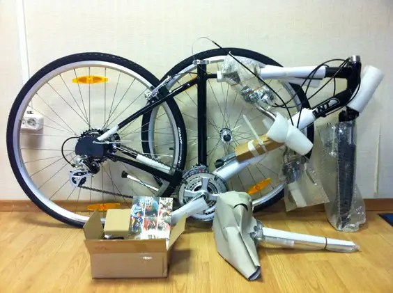
This is what the box with the bike looks like when it came from the factory. All bikes usually come pre-installed with a crankset, chain, rear and front derailleurs, rear wheel, brakes and steering column.
The steering wheel, seat, front wheel, pedals, reflectors and other small items are packaged separately.
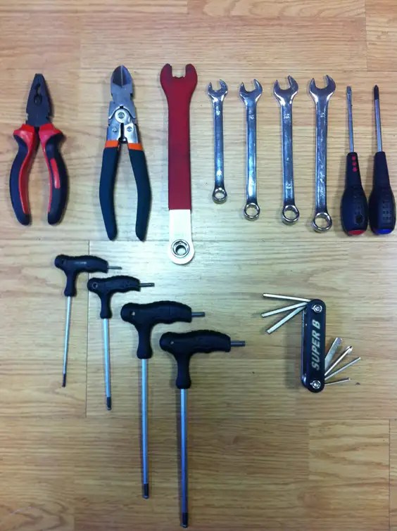
To assemble the setup you will need a number of tools:
- hexagons (4, 5, 6 mm), or better yet a set,
- wrench 15 (for tightening pedals),
- key for 10,
- Phillips screwdriver,
- pliers (for crimping the cable),
- wire cutters (for cutting the cable).
We take the bike out of the box. Using wire cutters or powerful scissors, cut off all the plastic clamps and remove the packaging. Be careful - at this stage it is easy to damage the paintwork of the frame.

First, attach the saddle to the seatpost. To do this, use a 6mm hexagon to unscrew the mount on the seatpost, install it in the grooves of the saddle frame, close it with a bracket on top and tighten it. This clever design also allows you to move the saddle back and forth and adjust the angle. Now you just need to tighten the bolt, and the settings will be more convenient to do on the assembled bike.

We fix the reflector as close as possible to the saddle.

We lower the entire structure into the seat tube to the end and secure it with an eccentric clamp. If it closes too easily, then open it all the way, tighten the tightening wheel and try to close it again. If it doesn’t close, on the contrary, we weaken it.

Next we'll deal with the stem and handlebars. It happens differently on different bikes: either the stem is already attached to the handlebars or not. In any case, the stem is installed first. When installing the stem and handlebars, pay attention to the shifter and brake cables - they should not be tangled. Pay attention to the vertical marks on the handlebar stem - this is the maximum possible lift height.

This little plug hides an important bolt! Using a 5 or 6 hex, the stem is secured in the steering column, and the steering wheel is height adjustable.


Let's take care of the front wheel. First you need to install the eccentric correctly (it is in a box with small things). The photo shows the correct position of all elements. Pay attention to the springs - they are located with the narrow part facing inward, i.e. to the wheel.

Remove the plug and spring from one side of the eccentric (the one where there is no lever) and insert the axle into the front wheel hub. The question may arise, which side should you insert it in? Just look at which side it is installed on the rear wheel (usually the left) and do the same.

Next, insert the wheel into the fork. It is necessary to “unfasten” the front brake of the bicycle in advance (in the case of rim brakes) or remove the elastic band from it (usually in the original packaging it is secured with an elastic band or tie).

It is most convenient to tighten the eccentric by approaching the bike from the front. In this case, you can monitor whether the wheel is centered. Tightening is done as follows: turn the wheel on the left clockwise and try to close the lever. If it closes very easily, fold it back and tighten the wheel again until the eccentric closes with force. There is no need to overdo it, otherwise you may break the eccentric!

Now you can pump up the wheels. The recommended pressure is always indicated on tires in psi and bar. Bar = atmosphere. Please note: the pressure in the bicycle wheels must be 3 atmospheres or higher. 3.5 is the best option. 2.2 like in cars is no good. During operation, periodically check the pressure in the wheels - this is the key to avoiding “eights”.
Let's install the pedals. The photo shows that each pedal is labeled L or R. Sometimes stickers are also attached. L (Left) - left, R (Right) - right. Be careful: the pedals have different threads! Both pedals are twisted “according to the movement” of the bicycle, i.e. the left one is to the left (counterclockwise), and the right one is to the right (clockwise).

First we tighten them by hand, and then tighten them with a 15 wrench.

If the chain is not in place, it can be easily returned there. To do this, press the rear derailleur tab and the chain weakens. Now you can simply pick it up with your hand and put it on one of the front sprockets.

Installation and adjustment of the front brake; adjusting both brakes
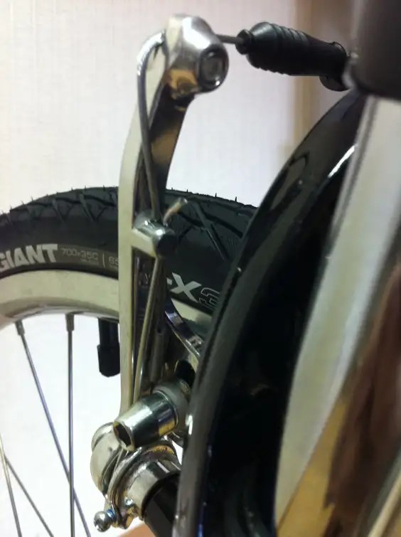
Now let's install the front brake. Find a curved tube like this in the box. You need to thread the front brake cable into it so that the wide part is at the top, and the narrow tip at the bottom is closer to the brake levers (in the next photo).

We do it as in the photo. The rubber band must be put on before screwing the cable. The rubber band is needed to protect the cable from dirt.

Now loosen the bolt and insert the cable there.

We squeeze the levers so that there is 2-3 mm left from the pads to the rim. and tighten the bolt (without fanaticism, otherwise the cable will start to “fluff”).

We leave a small part of the cable (5-7cm), cut the rest with wire cutters (you need very good wire cutters, otherwise the wire will fluff up at the end). Next, put on the tip and clamp it with pliers. If you don't have the right tools at hand, do this step later. But don’t put it off for too long - the cable may become fluffy and you will have to change it.

Now you need to adjust the brakes. It would be nice to devote a separate article to such a difficult issue, but now I will try to briefly describe the adjustment process.
The precise operation of the brakes consists of many nuances. First, spin the wheel (after inflating it to the recommended pressure) - is there a figure eight? If there is, then it needs to be corrected. It is better to do this by an experienced master or look for an article on eliminating eights on the Internet. If everything is in order, we move on.
When assembled, the brake pads should be at equal distances from the rim. This is achieved by tensioning the cable - you can loosen the bolt with which you secured the cable and tighten it more tightly. And there is also a “lamb” - it is located right next to the brake handle - it can also be used to tighten or loosen the cable. Never twist it all the way! The pads themselves should be parallel to the rim. Check if this is true. If not, you need to loosen the bolt securing them and adjust their position (see photo). You can, for example, hold the brake (then the pads will be pressed parallel to the rim) and immediately tighten the bolts.

Now press the brake lever and watch how the brake levers converge. And they must converge at the same time! Look at the video.
If, when you press the brake lever, one lever presses the pad faster than the other, you need to make adjustments with special screws (see photo). The adjustment is made as follows: select the lever where the block is pressed faster and stronger against the rim and tighten the screw on this side clockwise one or half a turn. Click and see if the situation changes. Typically, the pads begin to press against the rim simultaneously after adjustment with one screw. If not, then turn the screw on the other lever (where the block is further from the rim) counterclockwise by one to half a turn. Continue the steps described until you achieve the result as in the video. The same procedure must be done with the rear brake.

Adjusting the rear and front derailleurs
Now all that remains is to configure the switches and soon you can go for your first test drive. The adjustment of the switches must begin from the rear. The front one is usually well adjusted from the factory. To make adjustments, you will need a stand to place the rear wheel on, or an assistant to lift the bike by the saddle so you can pedal and see how everything works.
First, check to see if the rear derailleur requires adjustment. To do this, set on the front derailleur first (smallest sprocket) and alternate gears in the back while turning the pedals. If the chain does not rise or fall well on the sprockets, adjustment is required.
You need to start by adjusting the spring tension in the O m rear derailleur (or make sure it is adjusted correctly from the factory). To do this, set the front and rear derailleurs to the first star (number 1 on the derailleur handles). Those. in front it is the smaller star of the three, and in the back it is b O the lowest of seven (or eight, nine). Rotate the pedals until the chain fits onto the desired sprockets. Now pay attention to the H (High) and L (Low) screws on the rear derailleur. H - high gears, for example seventh; Low - lowered, for example the first one.

Since we have set it to first gear (low), our attention should be paid to screw L. Before we turn it (or maybe not at all), we need to make sure that the rear foot of the switch is exactly opposite the first star ( see photo). In the photo below, the chain is on the second sprocket so you can see the misalignment more clearly. The chain must be on the first sprocket!

If everything is smooth, you're in luck! If not, turn screw L one way or the other. You should see the switch foot begin to slowly move left or right. You know the task - the stars in the switch foot must lie in the same plane as the first star of the cassette. After you adjust the derailleur position with screw L, set the rear and front derailleur to the last sprockets and repeat the procedure with screw H.

Now let's start tensioning the chain. If the chain does not rise well from 7 to 1, then you need to slightly tighten the cable. If it doesn’t go down well from 1 to 7, then the cable is too tight and needs to be loosened. Necessary adjustments can be made using the adjustment wheel on the rear derailleur. Kr at Turn counterclockwise to tighten the cable, clockwise to loosen it. Again, don't overdo it or the wheel will just pop out of the switch. If the desired effect could not be achieved, then you need to loosen the nut 9 holding the cable, tighten/loosen the cable and secure it again.

The front derailleur is configured in a similar way. Only with screws H and L everything is the other way around: a small star is screw L, a large one is screw H.

I hope everything worked out for you! If not, don't despair. Look for specialized articles on the Internet, or seek help from an experienced bicycle mechanic. We, in turn, will try to make detailed articles for each stage. Good luck with the setup and have a nice trip ;)
Please leave your feedback and comments in the comment form below. The text and photographs of the article will be revised if necessary.
Anyone knows what a bicycle is, and almost everyone has owned one. In the modern world, this vehicle has gained wide popularity. This is due to both the maneuverability of the bike and the protection of the environment, as well as cost savings. Larsen bicycles from a Russian manufacturer (under license from a company from Finland) are considered one of the best in their class. The reliability of the models is ensured by the presence of a frame and fork made of reinforced steel. A wide range of models allows you to choose a modification according to personal preference. Let's consider the lines of this brand, characteristics and consumer reviews.
Models for children
Larsen bicycles have several modifications for children and teenagers. Let's look at the brief characteristics of some representatives.
The Kids 12 Boys model was released in 2013 and is not equipped with special shock absorption, but has additional side wheels that provide stability. The fork design is rigid and the head tube is a non-integrated threaded unit. A single rim ensures normal operation of 12-inch wheels. The device is available in several colors.
The children's bicycle Larsen Buggy 20 belongs to the teenage category. It has the following parameters:
- Fork category - entry level.
- The design of the front shock absorber is spring type.
- The steering column is threaded and without integration.
- Shock absorber type - Hard tail.
- The frame is made of steel.
- Soft fork type - Zoom Bravo-327E.
- The beading cord is made of metal.
The Larsen Super Team Girl bike is aimed at teenage girls. At the same time, it belongs to the category of mountain bikes and is equipped with a soft fork and spring shock absorption. The threaded column measures 1.1/8 inches and the frame is made of steel.

Walking versions
These are the following models:
- Jet. This model has one speed, is equipped with a foot and sleeve brake with steel elements. Aluminum rims comply with 6061-t6 standard. The modification is not equipped with additional front and rear brakes. A footrest and reflectors are available as additional equipment. Series colors - gray or white.
- Forest. These Larsen bikes are equipped with a coaster brake, are available in green, and do not have additional gear shifters. The rubber used is “Vanda” format, the rims are made of aluminum. Additional equipment includes reflectors and a step.
- Villa. This modification is equipped with one speed, a curved steel frame, and a bushing foot brake. Available in red color, equipped with a footrest and reflectors, rubber type - WANDA p1069, speed switches are not provided.
Road riders and “tourists”
Larsen Frenzy bicycles have a U-brake rear brake, double aluminum rims, anodized front hubs in an aluminum body. In addition, the model is equipped with a single-speed mechanism and reflectors.

The single-speed Tourist model has the following characteristics:
- Aluminum rims - type 6061-t6.
- Rubber - WANDA p p1027.
- Front and rear gear shifters are missing.
- Brake type - foot hub assembly.
- Additional equipment - running board and reflectors.
- Colors - gray or blue.
Way is a model aimed at cycling on asphalt and dirt roads. The frame is made of steel, the rims are made of aluminum. Braking is provided by steel foot bushings. Equipped with wings, a bell, reflectors, and a footrest.
Characteristics of the Way modification:
- Year of release - 2016.
- Drive - chain.
- There is no depreciation provided.
- Wheels - 20 inches.
- Steering wheel type - adjustable with threaded column.
- The pedals are a classic design.
- There is a rear rack and chain guard.
- Color design - red and white.

Mountain modifications
These are the following models:
- Mountain bike Larsen Rapido. The bike is designed for cross-country, released in 2011. The adult model has a steel frame, Hard Tail shock absorption, and a Zoom Bravo soft fork. In addition, there is an independent threaded steering column and 26-inch wheels.
- "Raptor" This model was released in 2013 and belongs to the teenage category of mountain bikes. The modification is equipped with a 1.1/8-inch steering column, a comfortable saddle, dual-suspension shock absorption, and a threaded column. Also included is a spring/elastomer fork, steel frame and single rim.
- Adult mountain bike Larsen Fighter released in 2013. It is equipped with a steel frame, a threaded steering column, and an entry-level spring-elastomer fork. There is a curved steering wheel and a six-position gear wheel. The rest of the equipment is comparable to the Raptor model.

Other representatives of the Larsen series
Below are the characteristics of the AvanGarde model:
- Year of release - 2012.
- Type - mountain (MTV).
- Category - for adults.
- The fork is an adjustable spring type.
- The steering column is threaded (1.1/8 inches).
- The fork design is a spring with an elastomer.
- Cushioning - Hard tail.
- Wheels - aluminum 26-inch rim.
- Braking system - front walking and rear rim unit.
- Number of speeds - 21.
- Shifters - Shimano Tourney TZ-30.
- Steering wheel type: curved.
The adult analogue of the Larsen Buggy bicycle is the Offroad model. It belongs to the adult category, is equipped with an entry-level soft spring fork, shock absorption with a pair of suspensions. There is also a threaded steering column, 26-inch aluminum wheels, and walking front and rear brakes. The 18-speed bike is equipped with a Shimano Tourney shifting system with a six-ring cassette.
Larsen bicycle: reviews
Consumer reviews about this series are mixed. This is not surprising, since the manufacturer presents a wide selection of models, ranging from children's and inexpensive recreational bicycles to multi-speed mountain models.
Many consumers note the reliability of the frame and ease of operation of the bike. Among the advantages: durability, ease of fit, original design, large selection of colors. Some owners include the disadvantages of not always good chain tension on single-speed modifications, a quiet bell sound and a simple body kit. However, there are not many complaints about the mountain models, since they are equipped with the Japanese Shimano gear shift system, which is considered one of the best in the world.
Finally
The brand in question was created in Finland, production is established in China and Russia. Larsen bicycles have gained popularity among domestic consumers due to their reliability, original design and wide range. At the same time, bicycle bikes of this brand are leaders in terms of the combination of quality and price indicators. Among the presented models, you can choose an option for a child from three years old, an active adult who loves extreme sports. The collection also includes options for leisurely city trips and tourism. Manufacturers have not forgotten about the better half of humanity. For women, there are universal walking modifications and mountain bikes aimed at young girls.
Size: px
Start showing from the page:
Transcript
2 This manual applies to FORWARD brand bicycles of the following models: Team; eleven; 12; 1212; 1222; 1230; 1240; 1312; 1322; 1332; 1340; 1412; 1410; 1422; 1420; 1432; 1430; 1430 lady; 1440; 2210; 2250; 2260; 5312; 5320; 5330; 5340; 5450; 3810; 3820; 3830; 9212; 6410; 6420; 6430; 7410; 4212; 4312; 4412; 4420; 8310; 910; SKIF 201; SKIF 202; SKIF 203; SKIF 204; MILAN 101; MILAN 102; SCORPION 100; ARSENAL 101; ARSENAL 102; ARSENAL 132; OMEGA 101; OMEGA 162; VEGA 101; VEGA 162; ENIGMA 103; ENIGMA 163; ENIGMA 154; SKIF 20; ALTAIR 401; ALTAIR 462; SEVILLA 401; SEVILLA 462; VALENCIA 401; VALENCIA 432; SKIF 24; DERBY 701; DERBY 762; DERBY 732; PARMA 700; PARMA 760; DORTMUND; CAPELLA; CAPELLA 060; BAVARIA; PORTSMOUTH 001; SKIF 28 woman; SKIF 28 man; BARCELONA 763; UNIT 201; UNIT 265; MAJORCA 261; MAJORCA 265; MAJORCA 286; COMANCHE 265; TITAN 565; TITAN 586; DAKOTA 581; DAKOTA 585; ROTOR 561; ROTOR 565; TWISTER 685; CAMINO 733; CAMINO 733; CAMINO 784; MASAI 885 SPORTING 885; SPORTING 885; SPORTING 886; SPORTING 817; SPORTING 818 disk; KATANA 861; KATANA 885; KATANA 886 disk; FLASH 863; FLASH 867; FLASH 888; FUSION 861; FUSION 883; FUSION 885; FUSION 817; STORM 817; APACHE 885; APACHE 886; APACHE 816; NEXT 887; NEXT 818 disk; HESPER 817; BURAN 365; VOLCANO 365; VOLCANO 386; CYCLONE 665; CYCLONE 686; TSUNAMI 665; TSUNAMI 686; BENFICA 985; BENFICA 987; BENFICA 988 disk; TERRA 917; TERRA 987; TERRA 918 disk; RAPTOR 987;RAPTOR 918; SPIKE 987; SPIKE 918 disk; STRADA 987; DUNDEE; BARSIK 16A; BARSIK 16B; SKIF 016; RACING 161; RACING 162; ACTIVE 161; ACTIVE 181;
3 SKIF 181; SKIF 182; LARSEN JUNIOR; LARSEN KIDS;LARSEN 101; LARSEN 102; LARSEN WAY; LARSEN JET; LARSEN RAPTOR; LARSEN TOURIST; LARSEN SUPER TEAM; LARSEN FIGHTER; LARSEN TRACK; LARSEN RAPIDO MEN; LARSEN RAPIDO WOMEN; LARSEN SUPER TEAM BASE; LARSEN SUPER TEAM ALTER; LARSEN RAPIDO MEN BASE; LARSEN RAPIDO MEN ALTER; LARSEN RAPIDO WOMEN BASE ; LARSEN RAPIDO WOMEN ALTER; LARSEN AVANTGARDE MEN; LARSEN AVANTGARDE WOMEN; LARSEN OFFROAD; LARSEN FOREST; LARSEN VILLA; CONGRATULATIONS ON YOUR PURCHASE OF A FORWARD BICYCLE! Your bike is well designed, assembled and adjusted so that it is safe to use and meets the highest standards. With proper care, your FORWARD will delight you for many years. Due to the fact that different FORWARD models are equipped with different equipment, this manual provides general and specific information. If you have any questions regarding the model or part of your bicycle, please contact your dealer. Assembly and initial adjustments require special tools and skill and should be performed by the dealer's experienced mechanic. Some operations can only be performed by a professional mechanic. Since a bicycle is a vehicle, safety rules cannot be neglected. The next chapter contains useful information to help you drive as safely as possible. Read this chapter before boarding your new FORWARD.
4 1. SAFETY 1. REMEMBER! Cycling is a potentially hazardous activity. 2. Before each ride, check the serviceability of the bicycle as described in the section When riding, use personal protective equipment. A helmet minimizes the likelihood of a head injury, goggles will protect your eyes from dust and insects, and gloves will protect your hands in case of a fall. 4. cross the rails at right angles. 5. do not use sprocket combinations that cause significant chain misalignment (for example, large front/large rear, or vice versa, small front/small rear). 6. When shifting, apply minimal load on the pedals. Otherwise, the life of the transmission as a whole is significantly reduced. 7. When shifting, do not try to shift into several gears at once. Switch gradually. 8. When riding, always take a pump and a spare tube (or repair kit) with you. Remember, riding on a flat tire will cause serious damage to your bike tire and tube. 9. To avoid theft, never leave your bike unattended. Never ride a faulty bike. 2. BICYCLE CONSTRUCTION saddle stem handlebar shifter seatpost tire frame brake handle steering column fork tire rim rim rear brake cassette front derailleur pedal front brake rear derailleur chain connecting rod front sprockets front hub 4
5 3. ASSEMBLY OF THE BICYCLE 1. remove the bicycle from the box and free it from packaging materials; 2. Install the front wheel. Make sure that the direction of the tire matches the direction of rotation, and use the eccentric correctly. 3. adjust the steering column; 4. adjust the front brake; 5. install pedals; 6.Adjust the front derailleur; 7. Stretch the connecting rod system; 8. adjust the rear brake; 9.Adjust the rear derailleur; 10. Inflate the tires. The assembly of the bicycle must be carried out by qualified mechanics in a specialized workshop or at the point of sale. 3.1 INSTALLING THE WHEELS 1. If the bicycle is equipped with V-Brake rim brakes, release the brake coupler and spread the brake levers to the sides (Fig. 1). 2. Unscrew the adjusting nut on the eccentric (Fig. 2), or the nuts on the wheel axle to such an extent that the wheel fits into the seats in the dropouts without resistance. 3. Tighten the nut on the eccentric coupler and fix the wheel by turning the eccentric lever with a torque N/m (Fig. 3). If the wheel is attached to the frame using nuts, fix the wheel in the dropouts by tightening the nuts on the axle with a force of N/m. 4. When installing the rear wheel on bicycles with one gear, it is necessary to ensure the necessary chain tension. Too little tension can cause the chain to fly off the sprockets; too much tension will result in heavy running and excessive chain wear. The normal tension should be such that the lower branch has a sag of 10-20mm, or when the upper branch is pulled back by hand, the deviation in the middle part is 20-25mm (Fig. 4). 7. When installing a rear wheel, the hub of which has a built-in brake (when braking is carried out by rotating the pedals backward), it is necessary to securely fix the brake lever of the hub on the lower left side of the frame using an integrated earring or clamp (Fig. 5). 8. If your bicycle is equipped with V-Brake rim brakes, after installing the wheel, close the brake levers and engage the brake coupler (Figure 6). Check the operation of the brake, if necessary, adjust the position of the brake pads (section 3.6). Do not try to lock the wheel by rotating the eccentric lever! It is strictly prohibited to use a bicycle with an unsecured brake coupler (for V-brake type brakes) or with an unsecured rear hub brake lever! 5
6 open brake coupler closed eccentric adjusting nut Fig. 2 brake lever Fig. 1 open dropout correct incorrect Fig. 3a closed eccentric adjusting nut Fig. 3 open closed Fig. 3b correct incorrect Fig. 3c mm Fig. 4 earring (clamp) rear bushing brake coupler fixing bolt brake lever fig.5 rim brake lever fig.6 6
7 3.2 ADJUSTING THE STEERING COLUMN 1. make sure that all assemblies of the steering column are assembled correctly and are in place (Fig. 7). 2. Using the armature screw, tighten the steering column to a level where the fork rotates in the steering column easily and without play. 3. Align the stem with the front wheel and tighten the fixing screws (Fig. 8). anchor screw steering column cover anchor screw steering column cover stem fixing screw stem steering column steering column Fig. 7 If the bicycle has a threaded type steering column: 4. make sure that all steering column assemblies are assembled correctly and are in place (Fig. 9). 5. Set the required stem height, align the stem with the front wheel and tighten the fixing screw. 6. Pay attention to the mark limiting the height of the stem lift. Raising the stem above this mark is unacceptable. fixing screw fig. 8 stem steering column 7 wedge nut fig. 9
8 3.3 INSTALLING THE PEDALS 1. Before adjusting the bike, install the pedals. This will make it easier to configure the switches. 2. By the markings on the pedal axle, determine which one is right and which is left (Fig. 10) (L-left, R-right). 3. Install the pedals according to the markings and use a 15mm open-end wrench to tighten them, applying force N/m (Fig. 11). Failure to comply with the tightening torque may result in damage to the threads during installation or during operation. left pedal right pedal pedal key L R Fig. 10 pedal connecting rod On the right pedal there is a right-hand thread, on the left there is a left-hand thread. key fig ADJUSTING THE FRONT SWITCH 1. Install the front derailleur on the seat tube so that the derailleur frame is parallel to the plane of the chainrings and the distance from the outer frame of the derailleur to the large chainring is 2-4 mm (Fig. 12), (Fig. 13). 2. Install the chain on the smaller sprocket on the crank and the larger sprocket on the cassette. 3. Using the adjusting screw L(low), adjust the extreme inner position of the front derailleur so that the chain is at a distance of 1-2mm from the inside of the frame (Fig. 14). 4. Setting the left shifter to the small star position, fix the front derailleur cable so that there is no free slack in the cable (Fig. 15). 5. Rotating the cranks forward, install the chain on the large sprocket on the crank and the small sprocket on the cassette. 6. Using the adjusting screw on the shifter, achieve smooth operation of the front derailleur (Fig. 16). 7. Using the adjusting screw H(high), adjust the outermost position of the front derailleur so that the chain is at a distance of 1-2 mm from the outer side of the frame (Fig. 17). 8
9 front derailleur frame front chainring derailleur 2-4 mm. big star front derailleur frame fig.12 fig mm. cable fixing screw adjusting screw L (low) front shift frame largest sprocket smallest sprocket cassette front sprockets chain Fig. 14 Fig. mm. left shifter adjusting screw Fig. 16 adjusting screw H (high) front shift frame smallest sprocket largest sprocket Fig. 17 cassette front sprockets chain 9
10 3.5 ADJUSTING THE REAR SWITCH 1. Before adjusting the rear derailleur, make sure that the rear derailleur mounting element (cock) is not deformed and the frame with rollers is parallel to the plane of the cassette sprockets (Fig. 18). 2. Rotating the cranks forward, set the right shifter to the small sprocket position, install the chain on the smallest sprocket on the cassette. 3. Set the cable tension adjustment screw on the shifter or switch to the middle position (Fig. 19). 4. Using the adjusting screw H(high), adjust the outermost position of the rear derailleur so that the upper roller of the rear derailleur is located exactly under the smallest sprocket (Fig. 20). 5. Fix the rear derailleur cable so that there is no free slack in the cable (Figure 21). 6. Rotating the cranks forward using the shifter, install the chain on the large sprocket in the cassette. 7. Using the adjusting screw L(low), adjust the extreme inner position of the rear derailleur so that the upper roller of the rear derailleur is strictly under the large sprocket in the cassette (Fig. 22). 8. Using the adjusting screw on the shifter, achieve smooth operation of the rear derailleur (Fig. 19). rear view of cassette sprocket cock right shifter frame with rollers cable tension adjustment screw rear derailleur Fig. 18 Fig. 19 incorrect correct incorrect rear view of cassette sprocket smallest sprocket cable fixing screw adjusting screw H (high) 10 frame with rollers Fig. 20 Fig. 21
11 rear view largest star adjusting screw L (low) frame with rollers fig ADJUSTING RIM BRAKES 1. Install the brake pads so that the braking surface of the pad is parallel to the braking surface of the rim and located exactly in the middle (Fig. 24). 2. Screw the adjusting screw on the brake lever all the way (Fig. 25), and fix the cable on the brake lever so that the distance between the pads and the rim is 1-2 mm (Fig. 26). 3. While pressing the brake lever, if necessary, use the adjusting screw to adjust the distance between the brake pads and the wheel rim (Fig. 25). 4. Using the adjusting screws on the brake levers, achieve uniform spread of the brake levers (Fig. 27). 5. As the brake pads wear and the cables stretch, adjust the cable tension using the adjusting screw on the brake lever or using the cable fixing screw on the brake lever, but do not allow the adjusting screw to be screwed into the brake lever less than 5 mm . 6. When the brake pads wear to the point where the grooves disappear, the pads need to be replaced (Fig. 28). side view top view front view brake pad brake pad brake pad wheel rim wheel rim wheel rim correct correct correct 11 incorrect incorrect incorrect Fig.24
12 brake lever fixing screw cable adjusting screw Fig. 25 brake pad wheel rim brake lever 1-2 mm. fig.26 brake pad operating condition brake lever adjusting screw fig.27 wear fig ADJUSTING MECHANICAL DISC BRAKES 1. Before adjusting the disc brakes, make sure that the brake discs are not deformed and that the brake pads are smooth and free of burrs. 2. Using manual-visual control methods, install the disc brake calliper so that the braking surface of the pads is strictly parallel to the plane of the brake disc. 3. Using the adjusting screw, install the stationary brake pad so that it is as close as possible to the brake disc, but does not touch it when the wheel rotates (Fig. 30). 4. Adjust and fix the brake cable so that when you press the brake lever, it does not reach the steering wheel 2-3 cm. (Fig. 31), if necessary, use the adjusting screw on the brake lever (Fig. 29). 5. As a rule, complete grinding in of disc brakes occurs after kilometers. brake lever 12 adjusting screw Fig. 29
13 adjusting screw fixed brake pad fixing screw brake calliper cable brake disc brake calliper movable brake pad fixed brake pad brake disc Fig. 30 Fig ADJUSTING HYDRAULIC DISC BRAKES 1. Before adjusting hydraulic disc brakes, make sure that the brake discs are not deformed and the brake pads are straight and have no burrs. 2. Using manual-visual control methods, install the disc brake calliper so that the braking surface of the pads is strictly parallel to the plane of the brake disc (Fig. 32). 3. Adjust the brake lever using the adjusting screw so that when pressed it does not reach the steering wheel by 2-3 cm (Fig. 33). 4. As a rule, complete grinding-in of disc brakes occurs after kilometers. It is recommended to change the hydraulic line and replace the brake fluid/oil only in a specialized workshop. brake calliper adjusting screw fig. 32 hydraulic line brake handle fig. 33 brake pads brake disc 13
14 3.9 INFLATING THE WHEEL 1. Before using the bicycle, inflate the wheels to the recommended pressure. The recommended pressure is indicated on the side of the tire. 2. Use a pump that fits your bike's nipple. There are two main types of nipples: bicycle (PRESTA) and automobile (SCHRADER) (Figure 34). 3. Before inflating a bicycle tire with a PRESTA nipple, loosen the safety screw (Fig. 35) and make sure it works by briefly pressing it. After inflating a bicycle tire with a PRESTA nipple, tighten the safety screw. open closed safety screw automobile nipple (schrader) bicycle nipple (presta) fig. 34 bicycle nipple (presta) fig. MONITORING THE CONDITION OF THE BICYCLE 4.1 Before each ride: 1. check the tire pressure; 2. check the operation of the brakes; 3. check the operation of the switches; 4. Stretch the connecting rods with a force of N/m (in the first week of use). 4.2 Weekly: 1. check the tightness of the steering column; 2. check the condition of the cables and jackets; 3. check the degree of wear of the brake pads; 4. Lubricate the chain. 4.3 Once a month: 1. check the condition of the transmission, chain, sprockets; 2. check the fixation of the saddle, seatpost, handlebars and stem; 3. check the condition of the steering column bearings for play; 4. check the condition of the pedal bearings for play; 5. check the condition of the wheel hub bearings for play; 6. check the condition of the carriage for play; 7. Pull the connecting rods with a force of N/m.
15 This chart is valid for normal use of the bicycle. If you often use your bike in rain, snow or on muddy roads, you should check and service the components more often. If any part becomes unusable, it must be replaced immediately. Never ride a faulty bike. 4.4 CHAIN LUBRICATION 1. Thoroughly clean the chain from dirt and dust using a cloth. The use of solvents and special degreasers is recommended. 2. Using an oil can, apply a drop of oil to each chain roller. 3. Rotating the pedals backwards, ensure that the lubricant penetrates into the chain between the rollers and the side plates of the links. 4. Use a rag to remove excess lubricant from the chain. An unlubricated chain has a significantly shorter lifespan and cannot ensure smooth operation of the switches. 15
16 5. WARRANTY OBLIGATIONS Before starting operation, carefully read the operating instructions and carefully follow all the stated requirements. The specified service life of a bicycle is 5 years. The warranty period for the bicycle is 12 months, the attached equipment is 6 months (from the date of sale of the bicycle). During the warranty period, bicycles that fail due to the fault of the manufacturer are repaired free of charge. To troubleshoot problems, the consumer must contact the warranty workshop or the seller. This warranty is valid if the warranty card is filled out correctly and legibly, indicating the serial number of the bicycle frame, the date of sale and the seller’s stamp. Delivery of a faulty bicycle to warranty service points is carried out using the efforts and means of the consumer. Bicycles are accepted for warranty repair only if they are clean and completely complete. 5.2 The warranty does not apply to: 1 Periodic maintenance of the bicycle; 2 For repair and replacement of parts associated with natural wear (lubrication, wear of bicycle tires, brake pads, suspension joints, etc.); 3 For radial and axial runout of wheels (figure eight) arising during operation; 4 For mechanical damage to any parts as a result of a fall or accident; 5 For damage associated with punctures, cuts, ruptures of tubes and bicycle tires. 5.3 The bicycle is removed from warranty service in the following cases: 1 Independent and unqualified repairs; 2 Inadequate care of the bicycle; 3 When changing the design of the bicycle; 4 When using a bicycle for commercial purposes (renting out, etc.) 16
17 6. BICYCLE PASSPORT Model: Serial number: Owner: Address, phone number: Date of sale: Seller's stamp: Special notes: I have read and agree with the terms of the warranty. I have no complaints about the appearance and configuration. Buyer: 17
18 18
19 FOR NOTES
20 Russia, Moscow region, Podolsk, st. Bronnitskaya, 3 tel.: +7 (495) tel/fax: +7 (4967) , Russia, Perm, st. Dzerzhinsky 59, Tel/fax +7 (342) ,
Page 1 This manual applies to bicycles of the FORWARD brand: hardtail team 1112, 1122, 1100 1212, 1222, 1230, 1240, 1200 1312, 1322, 1332, 1340 1412, 1410, 1422, 1420, 1432
USER MANUAL CONTENTS 1. GENERAL INFORMATION 1.1. Recommendations for use 2 1.2. Attention moms and dads 3 1.3. Rider Responsibility 4 2. OUTLEAP BICYCLES 2.1. Bicycle parts 5 2.2.
(English) DM-RD0002-00 RD-M280 Dealer's Manual IMPORTANT NOTE This dealer's manual is intended primarily for professional bicycle mechanics. Users not professionally trained in assembly
Instructions for assembling and using a MUSTANG bicycle. Printed at the State Enterprise Moscow Printing House of Goznak by order of TK SIMBA LLC. Order 1783. Signed for publication on July 17, 2003. Circulation 10,000 copies. Printing house
(English) DM-SL0002-03 Dealer's Manual Shifter REVOSHIFT SL-RS47 SL-RS45 SL-RS36 SL-RS35 SL-RS34 SL-RS25 IMPORTANT NOTE This dealer's manual is intended primarily for professional bicycle mechanic users.
(Russian) DM-TRSL001-01 Dealer's Manual HIGHWAY MTB Touring Bikes City Touring/ Comfort URBAN SPORT E-BIKE Shifter DEORE XT SL-T8000 DEORE SL-T6000 CONTENTS IMPORTANT NOTE... 3 TO ENSURE
Assembling a Fury bicycle out of the box Our company always monitors the quality of the bicycles it produces and strives to maintain not only the technical side, but also provide high-quality after-sales support
(English) DM-RBRD001-00 Dealer's Manual HIGHWAY MTB Touring Bikes City Touring/ Comfort URBAN SPORT E-BIKE Rear Derailleur CLARIS RD-R2000 CONTENTS IMPORTANT NOTE... 3 TO ENSURE SAFETY...
Bicycle operating manual Bicycle operating manual model In modification 14,356 mm 16,406 mm 18,457 mm 20,508 mm This “Manual” outlines the procedure for preparing for use,
(Russian) DM-UASL001-01 Dealer's Guide HIGHWAY MTB Touring Bicycles City Touring/ Comfort URBAN SPORT E-BIKE Shifter METREA SL-U5000 CONTENTS IMPORTANT NOTE... 3 TO ENSURE SAFETY...
Assembly and general maintenance of the bicycle Assembling the bicycle from the box. Includes configuration of all nodes. from Assembly from spare parts. Basic maintenance Complete maintenance Professional maintenance Diagnostics From new spare parts. No wheel assembly.
(English) DM-SL0004-01 Dealer's Manual Thumb Shifter Plus Thumb Shifter Plus SL-FT55 SL-TX50 SL-TX30 Thumb Shifters SL-TZ20 IMPORTANT NOTE This dealer's manual is intended to
Bicycle repair and maintenance on the road. Preparing your bike for a hike. Bicycle maintenance strategies 1) MTBF 2) Scheduled preventive maintenance 3) Forecasting and prevention
Instructions for assembling children's two-wheeled bicycles with wheel sizes from 12 to 20 ATTENTION! Equipping your bike with accessories and their appearance (water bottle, front and rear basket, bell, protective
BICYCLE OPERATION AND MAINTENANCE MANUAL CONGRATULATIONS ON YOUR PURCHASE OF AN OSCAR BICYCLE! Your bike is well designed, assembled, adjusted, so its use is safe and useful
Bicycle Bicycle. Assembled from factory packaging. Bike. Full assembly. Bike. Without suspension and suspension fork. Basic maintenance. Bike. Without suspension and suspension fork. Extended maintenance.
(Russian) DM-FD0002-05 Dealer's Manual Front Derailleur FD-9000 FD-6800 FD-5800 FD-4700 CONTENTS IMPORTANT NOTE... 3 TO ENSURE SAFETY... 4 INSTALLATION... 5 ADJUSTMENT... 9 TECHNICAL
(Russian) DM-MBST001-00 Dealer's Guide HIGHWAY MTB Hiking City Touring/ Comfort Bikes URBAN SPORT E-BIKE Shifter EZ-FIRE Plus ST-EF500 ST-EF510 CONTENTS IMPORTANT NOTE... 3 TO ENSURE
Exercise bike "VELOLIDER" Exercise bike owner's manual www.dcp-velo.ru CONGRATULATIONS ON YOUR PURCHASE OF AN EXERCISE BIKE VeloLeader! Your exercise bike is qualitatively designed, assembled, adjusted, so
BICYCLE OPERATION AND MAINTENANCE MANUAL CONGRATULATIONS ON YOUR PURCHASE OF A LARSEN BICYCLE! Your bike is well designed, assembled, adjusted, so its use is safe and useful
Contents DIAGRAM 2 PREPARATION 3 INSTALLING SIDE WHEELS 3 INSTALLING FRONT WHEEL 4 INSTALLING PEDALS 4 INSTALLING HANDLEBAR 5 ADJUSTING HANDLEBAR ANGLE 5 INSTALLING THE BASKET 6 INSTALLING THE SADDLE 7 CHECKING
1 This manual applies to bicycles for children of the FORWARD brand. 1. Description and operation of the product. 1.1. Purpose of the product. Bicycles are intended for preschool and younger children
BICYCLE OPERATION AND MAINTENANCE MANUAL CONGRATULATIONS ON YOUR PURCHASE OF A FORWARD BICYCLE! Your bicycle is well designed, assembled, adjusted, so its use is safe and
1 1.INTRODUCTION This manual applies to transport bicycle models of the FORWARD brand (see table 1): Table 1 2. DESCRIPTION AND OPERATION OF THE PRODUCT 2.1. PURPOSE OF THE PRODUCT Bicycles
(English) DM-MBSL001-00 Dealer's Guide HIGHWAY MTB Hiking City Touring/Comfort Bikes URBAN SPORT E-BIKE Shifter SLX SL-M7000 CONTENTS IMPORTANT NOTE... 3 TO ENSURE SAFETY... 4 CHECKLIST
(English) DM-FC0001-00 Dealer's Manual FC-M820 / FC-M825 SM-BB71 / SM-CR82 IMPORTANT NOTE This dealer's manual is intended primarily for professional bicycle mechanics. Users not
(Russian) DM-UAFD001-00 Dealer's Manual HIGHWAY MTB Touring City Touring/Comfort Bikes URBAN SPORT E-BIKE Front Derailleur METREA FD-U5000 CONTENTS IMPORTANT NOTE... 3 TO ENSURE
TM PIONEER TM PIONEER ÄÅÇÉÑÅÖÜÉ áàéâ, äãåç, ééèãåüåç. É Ç Å- Ä - - Ä ÄÅ Ç- - Terms of warranty for “PIONEER tm” bicycles Warranty obligations Dear
(English) DM-MBSL001-01 Dealer Manual HIGHWAY MTB Touring Bikes City Touring/ Comfort URBAN SPORT E-BIKE Shifter SLX SL-M7000 DEORE SL-M6000 CONTENTS IMPORTANT NOTE... 3 TO ENSURE SAFETY...
(Russian) DM-RARD001-03 Dealer's Manual HIGHWAY MTB Touring Bikes City Touring/ Comfort URBAN SPORT E-BIKE Rear Derailleur DURA-ACE RD-R9100 ULTEGRA RD-R8000 CONTENTS IMPORTANT NOTE... 3
(English) DM-HB0004-01 Dealer's Manual Road Disc Brake Hub HB-CX75 HB-RS505 FH-CX75 FH-RS505 IMPORTANT NOTE This dealer's manual is intended primarily for professional
(English) DM-HB0003-04 Dealer's Manual HIGHWAY Front Hub / 11-Speed Rear Hub HB-9000 HB-6800 HB-5800 FH-9000 FH-6800 FH-5800 IMPORTANT NOTE This dealer's manual is intended primarily for
(English) DM-BR0007-03 Dealer's Guide HIGHWAY MTB Hiking City Touring/ Comfort Bikes URBAN SPORT E-BIKE Mechanical Disc Brakes BR-TX805 BR-M375 CONTENTS IMPORTANT NOTE... 3 TO ENSURE
Thank you for purchasing a children's Premier Bike! We would like to draw your attention to the fact that a children's bicycle, as a product consisting of a large number of parts, for greater safety and security
(English) DM-BL0001-03 Dealer's Manual Dual Axle Clamp Brakes BR-4700 BR-4600 BR-3500 BR-2400 BL-R780 BL-4700 BL-4600 BL-3500 BL-2400 IMPORTANT NOTE This dealer's manual is intended primarily
(Russian) DM-RAFD001-04 Dealer's Manual HIGHWAY MTB Touring Bikes City Touring/ Comfort URBAN SPORT E-BIKE Front Derailleur DURA-ACE FD-R9100 ULTEGRA FD-R8000 105 FD-5801 Adjustment Procedures
(Russian) DM-SL0005-04 Shifter Dealer Manual RAPIDFIRE Plus 11 Speed MTB XTR SL-M9000 DEORE XT SL-M8000 CONTENTS IMPORTANT NOTE... 3 TO ENSURE SAFETY... 4 LIST OF ITEMS USED
(Russian) DM-RAFD001-03 Dealer's Manual HIGHWAY MTB Touring Bikes City Touring/ Comfort URBAN SPORT E-BIKE Front Derailleur DURA-ACE FD-R9100 ULTEGRA FD-R8000 105 FD-5801 Adjustment Procedures
(Russian) DM-HB0005-03 Dealer's Manual HIGHWAY MTB Touring Bicycles City Touring/ Comfort URBAN SPORT E-BIKE Front Hub/ Rear Hub (Disc Brake) HB-M4050 FH-M4050 HB-M3050 FH-M3050 HB-RM33
Nylga Mechanical Plant LLC UNIVERSAL SAW ATTACHMENT FOR SERIALLY PRODUCED CHAINSAWS NUP OPERATION MANUAL The universal saw attachment (hereinafter NUP) meets the requirements
Services provided by the SKILINE.bike Service Center pp. Types of work Cost of service, rubles Duration of execution Conditions Fork and steering wheel 1.1 Replacement of fork with anchor 650 is not urgent 1.2 Installation of siege anchor 200
Anatomy of a bicycle and its choice 1.1 Hardtail 1.Types of bicycles 1.2 Double suspension 1.3 Road bicycle 1.4 Hybrid 2.1 Frame 2.Anatomy of a bicycle A top tube; B down tube; With seat tube;
Bike Owner's Manual Congratulations on purchasing your Altair bike! Your bicycle is well designed, assembled, adjusted, so its use is safe and healthy.
(Russian) DM-RBBR001-00 Dealer's Manual HIGHWAY MTB Hiking City Touring/ Comfort Bicycles URBAN SPORT E-BIKE SORA BL-R3000 BR-R3000 Brake Cable BC-1051 Dual Axle Clamp Brakes CONTENTS IMPORTANT
INSTRUCTIONS FOR INSTALLING A MOTOR WHEEL ON A BICYCLE Contents Introduction Preparing the rear wheel Installing the tire Preparing the front wheel Installing the front/rear wheel Installing the brake levers Installation
(Russian) DM-RBMBR01-00 Dealer's Manual HIGHWAY MTB Hiking City Touring Bikes/ Comfort Bike URBAN SPORT E-BIKE Mechanical Disc Brakes Non-Series BR-RS305 CONTENTS IMPORTANT NOTE...
(English) DM-CD0001-00 Dealer's Manual Chain Tensioner SM-CD50 IMPORTANT NOTE This dealer's manual is intended primarily for professional bicycle mechanics. Users not professionally trained
BUZZY velomobile user manual ATTENTION! Small parts! Assembly only with adult participation. Save the instructions for future use. Article: 24.30.00.00 Introduction Congratulations
(Russian) DM-SL0001-09 Dealer Manual Shifter RAPIDFIRE Plus MTB XTR SL-M980-A SL-M980-A-I SL-M980-B-I SM-SL98-B SAINT SL-M820 SL-M820-I SL-M820-B-I SM -SL82-B DEORE XT SL-M780 SL-M780-I SL-M780-B-I
Choppy velomobile user manual ATTENTION! Small parts! Assembly only with adult participation. Save the instructions for future use. 49.90.00.26-3 Introduction Congratulations on your purchase
TRACTION WINCH CONTENTS Purpose of the product... 2 Delivery set... 3 Design of the product... 4 Main technical characteristics... 6 Preparation for work... 7 Operating procedure... 8 Recommendations for care
(Russian) DM-FD0001-03 Dealer's Manual Front Derailleur MTB FD-M670 FD-M671 FD-M675 FD-M676 FD-M785 FD-M785-E2 FD-M786 Touring FD-T670 FD-T671 FD-T780 FD-T781 HIGHWAY FD-3500 FD-3503 FD-A050 FD-A070
FORD MUSTANG GT velomobile user manual ATTENTION! Small parts! Not intended for children under 3 years of age. Assembly only with adult participation. Save the instructions for future use.
(English) DM-BR0009-00 Dealer's Guide HIGHWAY MTB Hiking City Touring/ Comfort Bikes URBAN SPORT E-BIKE Mechanical Disc Brakes BR-CX77 BR-CX75 BR-R517 BR-R515 BR-R317 BR-R315 CONTENTS IMPORTANT
JEEPAdventure Velomobile User Manual ATTENTION! Small parts! Not intended for children under 3 years of age. Assembly only with adult participation. Save the instructions for future use.
(Russian) DM-MBHB001-00 Dealer's Guide HIGHWAY MTB Touring Bikes City Touring/ Comfort URBAN SPORT E-BIKE Hub Kit (Disc Brake) SLX HB-M7000 HB-M7010 HB-M7010-B FH-M7000 FH-M7010 FH-M7010 -B
Nylga Mechanical Plant LLC PLANING MILLING ATTACHMENT FOR SERIALLY PRODUCED NFS CHAINSAWS OPERATION MANUAL The planing milling attachment (hereinafter referred to as NFS) meets the requirements
(Russian) DM-FD0003-05 Dealer's Manual Front Derailleur FD-M9000 FD-M9020 FD-M9025 FD-M8000 FD-M8020 FD-M8025 FD-M612 FD-M617 FD-M618 FD-M672 FD-M677 CONTENTS IMPORTANT... 4 TO ENSURE SAFETY...
(Russian) DM-MDFD001-02 Dealer's Guide HIGHWAY MTB Touring Bicycles City Touring/ Comfort URBAN SPORT E-BIKE Front Derailleur ALIVIO FD-M4000 FD-M4020 Non-serial FD-MT400 CONTENTS IMPORTANT NOTE...
Buzzy Bloom velomobile user manual Article 24.30.02.00 ATTENTION! Small parts! Assembly only with adult participation. Save the instructions for future reference. BERG Buzzy Bloom 1 1x
(English) DM-RAPD001-00 Dealer's Guide HIGHWAY MTB Hiking City Touring/ Comfort Bikes URBAN SPORT E-BIKE SPD-SL Pedals DURA-ACE PD-R9100 SM-PD63 CONTENTS IMPORTANT NOTE... 3 TO ENSURE
(English) DM-SL0003-00 Dealer's Manual SL-BSR1 IMPORTANT NOTE This dealer's manual is intended primarily for professional bicycle mechanics. Users not professionally trained in assembly
(Russian) DM-MBFD001-00 Dealer's Guide HIGHWAY MTB Touring Bikes City Touring/ Comfort URBAN SPORT E-BIKE Front Derailleur SLX FD-M7025 FD-M7020 FD-M7005 FD-M7000 CONTENTS IMPORTANT... 4 TO
Bike Owner's Manual Congratulations on purchasing your Forward bike! Your bicycle is well designed, assembled, adjusted, so its use is safe and healthy.
Figure 8 Tractor lubrication diagram 1 engine crankcase; 2 hydraulic system oil tank; 3 front propeller shaft bearing; 4 articulation pin bushings; 5 propeller shaft bearing; 6 bushings swivel
OPERATING INSTRUCTIONS Dear customer! Congratulations on your purchase of a modern and high quality Velolider bicycle that meets the highest standards. Please, before you start
LLC "Spetsenergokomplekt" SNOWMOBILE "ITLAN-KAYUR" Re-equipment for the introduction of reverse direction of movement Instruction ADVB.452243.002.004I 2 Contents Introduction 3 1 Safety measures 3 2 Disassembly 5 3 Rework
Mountain Bikes MEJIAS Passport (Owner's Manual) Mejias Mejias Mejias There is no road that leads to happiness, happiness is the road. Importer in the Republic of Belarus: LLC "Progress wholesale" RB, 220015, Minsk,
| Type | Hardtail |
| Floor | Unisex |
| Color | black blue |
| Wheel size | 26" |
| Number of speeds | 21 |
| Frame material | Steel |
| Front derailleur | Shimano Tourney (FD TZ-30) |
| Rear derailleur | Shimano Tourney (RD TZ-50) |
| Front bushing | Anteng sf-hb03fqr |
| Rear bushing | Anteng kt-122rqr |
| Shifters | Shimano SL-TX30, TOURNEY |
| Brake type | WinZip, V-shaped |
| Fork | MODE MD-721B |
| Fork travel | 50 mm |
| Rubber | Wanda P1197(A), 26"x2.125" |
| Rims | Wienmann XM2, double |
| Optional equipment | Reflectors, footrest |
| Maximum user weight | 95 kg |
| Brand | Larsen |
| Brand country | Finland |
| Manufacturer country | China |
| Guarantee | Frame (12 years) Attachments (6 months) |
The product may have slight differences from what is shown in the photo.
Mountain bike Larsen Rapido 26" - buy online
You can buy a Larsen Rapido 26" mountain bike in the Champion online store at an affordable price with online payment. Larsen Rapido 26" mountain bike detailed description with photos, characteristics, product reviews
Hello! What is included in this bike's warranty? I bought it for a child, and now one thing is broken, then another! All nuts need to be tightened, they are very weak. Bought in April 2018. The pedal itself is broken, the thread itself is broken, now you need to buy and replace the entire pedal holder! I'm disappointed with your brand! I will not buy such things from you again!
Good afternoon. The warranty on the attachment has not expired. Contact our service center.
Hello, do you sell bicycles on credit or in installments?
Good afternoon. Yes, all models where there is a credit or installment checkbox.
As far as I understand, this bike is not in the store now. How long will it cost if you order it? Is there a fee for ordering?
Good afternoon. Delivery times depend on the day of order and are calculated automatically on the website.
How long will it take for an order to reach the store? Is there an additional charge for ordering?
Good afternoon. Depends on what product you want to purchase. Delivery to a retail store is free, delivery times are calculated automatically on the website.
This model comes without wings. Are there suitable ones in stock?
Good afternoon. The appropriate wheel diameter is indicated in the fender product card. For example these are suitable:
Does this model have a kickstand?
Good afternoon. Yes, included.
Dear friends! Congratulations on your purchase of a bicycle. We wish you many pleasant hours spent with your bike on the roads and off-road.
The bicycles are designed using modern technologies and equipped with appropriate equipment. For normal operation of the bicycle, it is necessary to pay great attention to preventive inspection and, if necessary, routine repair of the bicycle.
When purchasing a bicycle, we advise you to make sure that the bicycle is properly assembled and that its components are working properly.
The store is responsible for the correct assembly and setup of the bicycle equipment.
FRAME SIZE
For a comfortable and safe ride, you need to choose the right frame size.
Frames are available in the following sizes:
|
For height, in cm |
Size, inches |
|
below 165 cm |
less than 16" |
|
165-185 cm |
16”-18” |
|
175-200 cm |
18”-20” |
|
over 190 cm |
more than 20" |
ATTENTION!
Like any mechanical vehicle, each bicycle and its equipment has a limited service life due to wear and tear on the chassis and stress on the frame and equipment during use. The durability of individual parts and assemblies may vary and depends on their design, materials of manufacture, maintenance and nature of use.
Drops (impacts) can have extreme impacts on the bicycle and its components. Jumping, performing various stunts, frequent riding in difficult off-road conditions, rain, snow, long downhill descents, and any other extreme use of a bicycle can be dangerous as the load on the frame increases. Extreme sports and cycling competitions captured on video are carried out by very experienced and professional riders using specially prepared equipment appropriate for this sport. Frequent and significant loads lead to premature fatigue of materials or sudden failure of the frame and components of the bicycle, which in turn can lead to loss of control of the bicycle while riding and injury.
Inspect your bike regularly. Scratches, cracks, dents, deformation of the frame or areas of the frame that have changed their color compared to the original are signs of heavy use of the bicycle. Although lighter frames and more expensive components have a longer lifespan than cheaper ones, they also require a lot of attention, since expensive bicycles and its equipment require more thorough and frequent maintenance.
Remember that you are at greater risk of injury from extreme riding, even if your bike is designed for such use. Therefore, use special protection, including a certified bicycle helmet.
USE A HELMET
An unprotected head is at great risk of injury, even from a minor impact. Wear a comfortable helmet that fits snugly and meets CE or CPSC safety standards. We also recommend wearing special safety glasses and cycling clothing.
HANDL YOUR BIKE WITH CARE BEFORE, DURING OR AFTER EACH RIDE
- Keep your bike clean. Regularly clean your bike and its equipment from dirt, sand, especially after riding in difficult off-road conditions, rain, snow, slush, etc. Avoid using high pressure car washers.
- Do not leave your bike outdoors for a long time under the influence of adverse weather conditions (rain, snow, direct sunlight, high humidity).
- Use a suitable bike storage facility. It is better to store a bicycle (for example, in winter) in a suspended state with the tire pressure reduced by half. Do not leave your bicycle in close proximity to sources of electromagnetic radiation (including electric motors), the operation of which negatively affects the condition of the tires and the finish of the bicycle.
- Your bicycle is a relatively expensive product, so we recommend the following:
1. Write down the serial number of the bicycle.
2. Register the bicycle with law enforcement agencies.
3. Lock your bike with a secure lock.
4. Do not leave the bicycle unattended, even for a short time.
- When storing the bike, shift gears to the smallest chainrings. This will reduce chain tension and relieve unnecessary pressure on the crank arms and rear derailleur spring.
- When driving, use the correct gear layout.
- Protect your bike from unexpected damage. When parking (resting), place the bicycle off the road and make sure it does not fall, do not place the bicycle on its side on the rear derailleur.
- Do not allow the steering wheel or fork to hit the frame due to large turns of the steering wheel.
- Never change the equipment, change the suspension fork, or make changes to the frame. All components and equipment of your bicycle are carefully selected by the manufacturer in accordance with the geometry of the bicycle frame and its operating conditions. Modifying any part of the bicycle may damage it and make it unsafe to ride. Please consult your dealer before making any changes. In case of any modification to the frame, fork or equipment of the bicycle, you will be denied service under the terms of the warranty.
EACH TIME BEFORE STARTING A TRIP, YOU MUST CHECK:
- CONDITION AND ALIGNMENT OF WHEEL
In order to check whether the rim is level or not, or whether the wheel is correctly installed relative to the fork/frame, you need to spin each wheel of your bicycle and see how the rim moves relative to the brake pads or frame elements. If you find a fault with one or both wheels, contact the bike shop/workshop.
- TIRE PRESSURE AND THEIR CONDITION
Inflate the inner tube according to the pressure indicated on the side of the tire. The upper value (maximum pressure) will provide your bike with good ride quality on hard and level road surfaces. The lower value (minimum pressure) will provide you with comfort, good traction and controllability off-road. Your weight and the weight of your luggage also plays a big role when inflating your tires. Lighter cyclists will probably get more comfort with low tire pressure, while heavier ones with a larger load will need higher tire pressure.
To determine the tire pressure, use hand pumps with a pressure gauge. Worn tires need to be replaced.
- RELIABILITY AND CORRECT POSITION OF BRAKES
Apply pressure on each brake lever to check how freely and smoothly the brake pads move and how the brakes perform. The brake pads must be parallel to the rim, centered on the side wall of the rim, without touching the surface of the tires. The distance between the pad and the side surface of the rim (with the brake lever not pressed) should be 2-3 mm.
- RELIABILITY OF WHEEL MOUNTING
Your bicycle may be equipped with a quick release mechanism. This mechanism allows you to quickly remove/install the wheel without tools. Make sure the handle of this mechanism is in the CLOSE position and holds the wheels securely.
THE FAILURE-FREE OPERATION OF A BICYCLE DEPENDS ON ITS OPERATING CONDITIONS AND REGULAR MAINTENANCE.
MAINTENANCE AND CURRENT REPAIRS
WEEKLY
- Wipe the bike and equipment thoroughly with a damp, soft cloth.
- Check spoke tension
- Lubricate the suspension fork
- Check that the suspension fork is securely attached to the frame
MONTHLY
- Carefully inspect the chain and cassette. Clean and lubricate.
- Inspect the switches carefully. Clean and lubricate.
- Check that all bolts and nuts are present:
- Nut (mechanism) for fastening the seatpost
- Nuts (bolts) for securing the saddle
- Handlebar and stem mount
- Attaching additional attachments (racks, fenders, bike computer, etc.)
- Carefully inspect the shift and brake cables for wear.
- Check brake pad wear, replace if necessary
- Check wheel bushings and steering column bearings
ONCE EVERY THREE MONTHS
- Carefully inspect and lubricate the brake lever mechanism
- Carefully inspect the connecting rods, tighten the nuts
- Carefully inspect the pedals, check the reliability of their fastening
- Check the fastening of the light reflectors
ANNUALLY
- Replacing the lubricant in the carriage, or replacing the cartridge
- Replacing the steering column lubricant
- Replacing the lubricant of the pedal mechanism and lubricating the thread connecting the pedal to the connecting rod
- Lubrication of the eccentric mechanism
- Seatpost Lubrication
- Stem lubrication
- Replacing the grease in the suspension fork
All recommendations for maintenance and repair refer to normal operating conditions of the bicycle. In the event that the bicycle was often used in rain, snow, etc. Maintenance and repair intervals must be reduced.
DESCRIPTION AND ADJUSTMENT OF INDIVIDUAL UNITS AND ELEMENTS OF THE BICYCLE
SADDLE
Before riding, you must set the correct height and position of the saddle. Set the saddle high enough so that the heel of your lowered leg just touches the pedal - leg straight, pedal at the very bottom of the revolution in line with the seat tube. For most people, this will give the saddle height such that the knee is slightly bent at the bottom of the pedal revolution. This will also prevent you from wobbling your hips with each revolution of the crank. This is the best approximation for saddle height. You can then continue to adjust the saddle height more precisely to suit your preferences and riding style. Seat height fixation is ensured by a seat eccentric, which is installed in the upper part of the seat tube of the frame. The saddle tilt is adjusted using a screw at the top of the seat. To do this, you must first loosen, then adjust the saddle, and then tighten the seat bolt nut.
Never extend the seatpost beyond the limit mark marked on it.
STEERING WHEEL
ATTENTION:
The height of handlebars with an A-HEAD stem cannot be changed.
ATTENTION:
Adjustable stem. The bicycle handlebar is adjustable both in height and inclination, which allows the cyclist to take the most comfortable position.
Adjustment is made using a screw on the steering wheel rod. After setting the optimal height and angle of the steering wheel, secure its position by tightening the screw tightly.
It is best to install the handlebars and saddle at the same level or lower the handlebars a little lower.
We recommend setting the maximum distance from the saddle to the handlebars and the lowest position in which you feel comfortable (with emphasis on COMFORTABLE).
PEDALS
The pedals are designated "R" (right) and "L" (left). The pedal marked "L" has a left-hand thread for the left crank, and the pedal marked "R" has a right-hand thread for the right crank.
Before riding a bicycle, check that the pedals are securely fastened. Some bikes are equipped with Shimano SPD pedals, which require special cycling shoes.
CHAIN
The chain serves to transmit torque from the pedals to the rear wheel. During operation, the chain must be kept clean and its wear monitored. A worn chain must be replaced. Long-term use of a worn chain causes greater wear on the cassette sprockets and crank sprockets. When replacing a heavily worn chain, you must also replace the cassette and connecting rods.
To ensure normal operation of the drive, we recommend using SHIMANO chains. You also need to pay attention to the type of chain: HG and IG.
An IG type chain cannot be replaced with an HG type chain. The chain is cleaned with special means - digesters or kerosene, after which it is lubricated with special lubricants. There should not be a lot of lubricant on the chain to avoid accelerated contamination.
CONNECTING ROD SYSTEM
The crank system consists of a right and left crank, a cartridge (axle with bearings) and pedals. The connecting rods are fixed to the axle. When purchasing a bicycle, the entire mechanism does not require additional adjustment.
If play in the connecting rods (not the carriage axle) appears, immediately remove the safety caps and tighten the screw or nut until it stops. Failure to tighten the bolts in a timely manner will result in the connecting rod breaking.
GEAR SHIFT
The mechanism consists of a front derailleur, which transfers the chain to one of the three sprockets of the crankset, and a rear derailleur, which transfers the chain to one of seven (eight, nine) small sprockets on the rear wheel hub. Gear shift control levers (shifters) can be either combined with the brake levers or separately. The right shifter is responsible for rear shifting, the left one for forward shifting.
Some bicycle models are equipped with a GRIP SHIFT control system, where instead of levers a rotary shift mechanism is installed on the handlebars.
In order to reduce wear and increase the service life of the gear shift mechanism, sprockets and chain, we recommend changing gears at the moment of minimum load.
When purchasing a bicycle, the gear shift mechanism is configured and prepared for operation. During the running-in of the bicycle, it may be necessary to make fine adjustments, which are done with the adjusting screw.
When changing gears, the chain should move smoothly over the sprockets without any sharp mechanical sounds. If problems arise with the gear shift mechanism, we recommend that you contact the workshop or store where you purchased the bike.
BRAKES
Bicycles are equipped with V-brake brakes with brake levers mounted on the fork (stays). They are highly efficient. Road (road) bicycles use clamp brakes, which does not reduce their effectiveness. The brake levers are mounted on the handlebar: the left one is for the front brake, and the right one is for the rear brake.
Since a mountain bike has a shortened base, in order to avoid throwing it over the handlebars when braking, especially during descents, we recommend applying more force to the rear brake (right brake lever), and only applying the brakes with the front brake.
When purchasing a bicycle, the brakes are installed in the working position and provide reliable operation.
ATTENTION:
Operate the bicycle only after making sure the brakes are working properly. Have any malfunctions resolved by a qualified technician at a repair shop.
Brake pads wear out due to friction, which reduces the distance between the pads and the wheel rim (normal distance is 2 - 3 mm).
Minor wear can be compensated for by adjusting the position of the pads using adjusting screws. Continued use of heavily worn pads leads to premature wear of the rim - so they must be replaced in a timely manner.
WHEELS
Most bicycles have wheel sizes (diameter) of 26" (559 mm) on mountain bikes and 28" (622 mm) on road bikes. The wheel hubs are equipped with eccentrics, which makes it possible, if necessary, to quickly and easily remove and install the wheel. To ensure safety while riding, the wheels must be securely fastened to the frame (fork) and correctly centered. In this case, the rim brakes will work most effectively.
The tire pressure must correspond to the value indicated on the tire, as well as the type of terrain on which the bicycle is used: on roads 3 - 4 atmospheres, off-road 2.5 - 3.5. Also on some tires an arrow indicates the direction of its movement.
ATTENTION:
In most cases, bicycles do not come with all the accessories so that you can participate in road traffic. They are intended for use outside public road communications. Therefore, if necessary, the bicycle can be equipped with a headlight/flashing light, fenders, luggage rack, bicycle computer, etc.
NOTE:
After 50 km, but no later than 3 weeks, provide the bike for a warranty inspection to check components and parts and adjust mechanisms.
Defects resulting from failure to comply with the above condition are not covered by warranty.
The bike comes with a WARRANTY:
on frame - 3 years;
for equipment - 0.5 years;
GENERAL PROVISIONS:
The seller confirms that the bicycle meets technical standards and requirements. The warranty period begins from the date of sale of the bicycle. Warranty repairs are carried out by a warranty workshop.
WARRANTY CONDITIONS:
The bicycle must be sold directly to the user assembled with pre-sale preparation, ready for use. Otherwise, the right to warranty is lost.
- The product must be used only for its intended purpose;
- The bicycle must be maintained according to the above recommendations;
- To fulfill warranty obligations, a warranty card must be presented;
- The warranty applies to frame, equipment, components with manufacturer defects. In this case, the defective part must be repaired or replaced
- The repair guarantees the customer the continued use of the bicycle.
- For warranty repairs, the bicycle must be provided complete and in clean condition.
- The workshop has the right not to accept a contaminated bicycle for repair.
The cost of the work of a bicycle workshop mechanic to replace equipment/components under warranty is paid additionally.
ATTENTION!
THE WARRANTY DOES NOT APPLY TO:
- normal wear and tear of materials, components and equipment;
- in case of improper use of the bicycle and its equipment;
- in case of breakdowns caused by falls, impacts, dents, ruptures, frame deformation, etc.;
- bicycles - equipment whose frames and suspension forks have been replaced or modified;
- wear of bearings as a result of untimely elimination of backlashes;
- defects in tires and tubes;
- worn (stretched) chain. The service life of the chain is approximately 1000 km.