Pyroelectric Infrared (PIR) Motion Sensor and Arduino. PIR sensor: description and connection instructions Arduino motion sensor
The topic of today's lesson is a motion sensor based on the pyroelectric effect (PIR, passive infrared motion sensor). Such sensors are often used in security systems and in everyday life to detect movement in a room. For example, the principle of motion detection is used to automatically turn on the lights in the entrance or in the bathroom. Pyroelectric sensors are quite simple in design, inexpensive and unpretentious to install and maintain. By the way, there are other ways to detect motion. Today, computer vision systems are increasingly used to recognize objects and the trajectory of their movement. The same security systems use laser detectors that give an alarm when the beam crosses. Thermal imaging sensors are also used that can detect the movement of only living creatures.
1. Operating principle of pyroelectric motion sensors
Pyroelectrics are dielectrics that create an electric field when their temperature changes. Temperature measurement sensors are made based on pyroelectrics, for example, LHI778 or IRA-E700. Each such sensor contains two sensing elements measuring 1x2 mm, connected with opposite polarity. And as we will see later, the presence of exactly two elements will help us detect movement. This is what the Murata IRA-E700 sensor looks like. In this lesson we will work with the HC-SR501 motion sensor, which has one such pyroelectric sensor installed. The pyroelectric is surrounded on top by a hemisphere, divided into several segments. Each segment of this sphere is a lens that focuses thermal radiation onto different areas of the PIR sensor. Often a Fresnel lens is used as a lens.
  The principle of operation of the motion sensor is as follows. Let's assume that the sensor is installed in an empty room. Each sensitive element receives a constant dose of radiation, which means the voltage across them has a constant value (left figure).
  As soon as a person enters the room, he first enters the viewing area of the first element, which leads to the appearance of a positive electrical impulse on it (central figure). A person moves, and his thermal radiation through the lenses reaches the second PIR element, which generates a negative impulse. The electronic circuit of the motion sensor registers these multidirectional impulses and draws conclusions that a person has entered the field of view of the sensor. A positive pulse is generated at the sensor output (right figure).
 2. Setting up HC-SR501
In this tutorial we will be using the HC-SR501 module. This module is very common and is used in many DIY projects due to its low cost. The sensor has two variable resistors and a jumper for setting the mode. One of the potentiometers adjusts the sensitivity of the device. The larger it is, the further the sensor “sees”. Sensitivity also affects the size of the detected object. For example, you can exclude a dog or cat from triggering. The second potentiometer adjusts the response time T
. If the sensor detects movement, it generates a positive pulse at the output with a length T
. Finally, the third control is a jumper that switches the sensor mode. Pregnant L
the sensor is counting T
from the very first operation. Let's say we want to control the light in the bathroom. Entering the room, a person will trigger the sensor, and the light will turn on exactly for a while T
. At the end of the period, the output signal will return to its original state, and the sensor will give the next response. Pregnant H
the sensor starts timing T
every time motion is detected. In other words, any human movement will reset the countdown timer T
. By default, the jumper is in the state H
.
The second potentiometer adjusts the response time T
. If the sensor detects movement, it generates a positive pulse at the output with a length T
. Finally, the third control is a jumper that switches the sensor mode. Pregnant L
the sensor is counting T
from the very first operation. Let's say we want to control the light in the bathroom. Entering the room, a person will trigger the sensor, and the light will turn on exactly for a while T
. At the end of the period, the output signal will return to its original state, and the sensor will give the next response. Pregnant H
the sensor starts timing T
every time motion is detected. In other words, any human movement will reset the countdown timer T
. By default, the jumper is in the state H
.
3. Connecting HC-SR501 to Arduino Uno
For connection to a microcontroller or directly to a relay, the HC-SR501 has three pins. We connect them to Arduino according to the following scheme:| HC-SR501 | GND | VCC | OUT |
| Arduino Uno | GND | +5V | 2 |
 Layout appearance
 Program As already mentioned, the digital output of the HC-SR501 sensor generates a high signal level when triggered. Let's write a simple program that will send “1” to the serial port if the sensor saw movement, and “0” otherwise. const int movPin = 2 void setup() ( Serial.begin(9600); pinMode(movPin, INPUT); ) void loop())( int val = digitalRead(movPin); Serial.println(val); delay(100); ) Load the program onto the Arduino and check the operation of the sensor. You can tweak the sensor settings and see how this affects its operation.
 4. Light control based on motion sensor
The next step is an automatic light switching system. In order to control the lighting in the room, we will need to add a relay to the circuit. We will use a relay module with protection based on optocoupler, which we already wrote about in one of the lessons (lesson about relays). Attention! This circuit lights the lamp from a 220 Volt network. It is recommended to check all connections seven times before connecting the circuit to the household power supply. Schematic diagram Layout appearance
 Program Now let’s write a program that, when the sensor is triggered, will turn on the relay, and therefore the lighting in the room. const int movPin = 2; const int relPin = 3; void setup() ( Serial.begin(9600); pinMode(movPin, INPUT); pinMode(relPin, OUTPUT); ) void loop())( int val = digitalRead(movPin); if (val) digitalWrite(relPin, HIGH) ; else digitalWrite(relPin, LOW); Load the program onto the Arduino, carefully connect the circuit to the household network and check the operation of the sensor. Conclusion Motion sensors are all around us. Thanks to security systems, they can be found in almost every room. As we found out, they are very easy to use and can be easily integrated into any Arduino or Raspberry Pi project. Here are a few situations and places where a motion sensor can come in handy:
 - automatic switching on of light in the entrance of the house, in the bathroom and toilet, in front of the entrance door to the room;
- alarm system indoors and in the yard;
- automatic door opening;
- automatic activation of the security video camera.
The Arduino motion sensor allows you to track the movement of objects that emit heat (people, animals) in a closed area. Such systems are often used in domestic conditions, for example, to turn on lighting in the entrance. In this article we will look at connecting PIR sensors in Arduino projects: passive infrared sensors or pyroelectric sensors that respond to movement. Small dimensions, low cost, ease of operation and lack of connection difficulties allow the use of such sensors in various types of alarm systems.
The design of a PIR motion sensor is not very complicated - it consists of a pyroelectric element that is highly sensitive (a cylindrical part with a crystal in the center) to the presence of a certain level of infrared radiation in the action area. The higher the temperature of an object, the greater the radiation. A hemisphere is installed on top of the PIR sensor, divided into several sections (lenses), each of which ensures that the thermal energy radiation is focused on different segments of the motion sensor. Most often, a Fresnel lens is used as a lens, which, due to the concentration of thermal radiation, allows you to expand the sensitivity range of the Arduino infrared motion sensor. 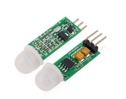
The PIR sensor is structurally divided into two halves. This is due to the fact that for an alarm device it is the presence of movement in the sensitivity zone that is important, and not the level of radiation itself. Therefore, the parts are installed in such a way that when one higher level of radiation is detected, a signal with a high or low value will be sent to the output.
The main technical characteristics of the Arduino motion sensor are:
- The detection zone for moving objects is from 0 to 7 meters;
- Tracking angle range – 110°;
- Supply voltage – 4.5-6 V;
- Operating current – up to 0.05 mA;
- Temperature range – from -20° to +50°С;
- Adjustable delay time from 0.3 to 18 s.
The module on which the infrared motion sensor is installed includes additional electrical wiring with fuses, resistors and capacitors.
The principle of operation of a motion sensor on Arduino is as follows:
- When the device is installed in an empty room, the radiation dose received by each element is constant, as is the voltage;
- When a person appears in a room, he first of all falls into the viewing area of the first element on which a positive electrical impulse appears;
- When a person moves around the room, thermal radiation moves along with him, which hits the second sensor. This PIR element already generates a negative pulse;
- Multidirectional pulses are recorded by the electronic circuit of the sensor, which concludes that there is a person in the field of view of the Pir-sensor Arduino.
 For reliable protection from external noise, temperature and humidity changes, the elements of the Pir sensor on Arduino are installed in a sealed metal case. On the top of the case in the center there is a rectangle made of material that transmits infrared radiation (most often silicone-based). Sensing elements are installed behind the plate.
Connection diagram of the motion sensor to Arduino
 Connecting a Pir sensor to Arduino is not difficult. Most often, modules with motion sensors are equipped with three connectors on the back. The pinout of each device depends on the manufacturer, but most often there are corresponding inscriptions near the outputs. Therefore, before connecting the sensor to Arduino, you need to familiarize yourself with the symbols. One output goes to ground (GND), the second provides the required signal from the sensors (+5V), and the third is a digital output from which data is taken.
Connecting a Pir sensor:
- “Ground” – to any of the Arduino GND connectors;
- Digital output – to any digital input or output of Arduino;
- Power supply – +5V on Arduino.
The diagram for connecting the infrared sensor to Arduino is shown in the figure.
Example program
A sketch is a program code that helps check the functionality of the motion sensor after it is turned on. His simplest example has many disadvantages:
- Probability of false alarms due to the fact that it takes one minute for the sensor to self-initialize;
- Lack of executive-type output devices - relays, sirens, LED indicators;
- A short time interval of the signal at the sensor output, which must be delayed at the software level in the event of movement.
These disadvantages are eliminated by expanding the functionality of the sensor.
The simplest type of sketch, which can be used as an example of working with a motion sensor on Arduino, looks like this:
#define PIN_PIR 2 #define PIN_LED 13 void setup() ( Serial.begin(9600); pinMode(PIN_PIR, INPUT); pinMode(PIN_LED, OUTPUT); ) void loop() ( int pirVal = digitalRead(PIN_PIR); Serial. println(digitalRead(PIN_PIR)); //If motion is detected if (pirVal) ( digitalWrite(PIN_LED, HIGH); Serial.println("Motion detected"); delay(2000); ) else ( //Serial.print(" No motion"); digitalWrite(PIN_LED, LOW); ) )
Possible project options using the sensor
PIR sensors are indispensable in those projects where the main function of the alarm is to determine the presence or absence of a person within a certain work space. For example, in places or situations such as:
- Turning on the light in the entrance or in front of the front door automatically when a person appears in it;
- Turning on the lighting in the bathroom, toilet, corridor;
- An alarm is triggered when a person appears, both indoors and in the local area;
- Automatic connection of security cameras, which are often equipped with security systems.
PIR sensors are easy to use and do not cause difficulties when connecting, have a large sensitivity zone and can also be successfully integrated into any of the Arduino software projects. But it should be borne in mind that they do not have the technical ability to provide information about how many objects are in the coverage area, and how close they are to the sensor, and can also be triggered by pets.
PrincipleworkPIR (Passive Infra Red)-sensors
Any object that has a certain temperature becomes a source of electromagnetic (thermal) radiation, including the human body. The wavelength of this radiation depends on temperature and is in the infrared part of the spectrum. This radiation is invisible to the eye and is detected only by sensors. They are also called PIR sensors.
This is an abbreviation for the words “passive infrared” or “passive infrared” sensors. Passive - because the sensors themselves do not emit, but only perceive radiation with a wavelength from 7 to 14 µm.
A person radiates heat. Its thermal image in infrared rays shows the temperature distribution over the surface of the body. Warmer objects appear lighter, colder objects appear darker, because... emit less heat.
The PIR sensor contains a sensing element that responds to changes in thermal radiation. If it remains constant, no electrical signal is generated.
In order for the sensor to respond to movement, special lenses (Fresnel lenses) with several focusing areas are used, which divide the overall thermal picture into active and passive zones located in a checkerboard pattern. A person, being in the area of operation of the sensor, occupies several active zones in whole or in part.
Therefore, even with minimal movement, movement occurs from one active zone to another, which triggers the sensor. The background thermal pattern usually changes very slowly and evenly. The sensor does not respond to it. The high density of active and passive zones allows the sensor to reliably detect the presence of a person even with the slightest movement.
Today we will analyze the project of connecting a PIR (motion) sensor to Arduino and organize automatic sending of an e-mail when the sensor is triggered. Arduino is the heart of this project - it reads the IR sensor, and when motion is detected, it commands the computer via the USB port to send an email. We process the signal entering the computer using the Python program.
List of parts for assembling the model
To assemble the project described in this tutorial, you will need the following parts:
- Arduino UNO or equivalent (read more about how to choose Arduino);
- PIR sensor (this one for $2 will do);
- Bradboard (can be purchased for $2.4);
- male-male wires (you can buy such a bundle with a large supply).


We will also need a computer with an Internet connection, through which we will send email! The role of the computer in this lesson can be played by.
Connection diagram for PIR sensor to Arduino
Only the PIR sensor needs to be connected to the Arduino in this project, so the wires from the sensor can be connected directly to the Arduino. But because In this case, the wires are held a little loosely, it is more convenient to use the diagram from the Bradboard:

Arduino sketch
Arduino will send a message via USB Serial communication when motion is detected. But if you send an e-mail every time the sensor is triggered, you can receive a huge number of letters. Therefore, if too little time has passed since the last signal, we will send another message.
int pirPin = 7;
int minSecsBetweenEmails = 60; // 1 min
long lastSend = -minSecsBetweenEmails * 1000;
void setup()
{
pinMode(pirPin, INPUT);
Serial.begin(9600);
}
void loop()
{
long now = millis();
if (digitalRead(pirPin) == HIGH)
{
if (now > (lastSend + minSecsBetweenEmails * 1000))
{
Serial.println("MOVEMENT"); lastSend = now;
}
else
{
Serial.println("Too soon"); )
}
delay(500);
}
The "minSecsBetweenEmails" variable can be changed to another reasonable value. In the example, it is set to 60 seconds, and emails will not be sent more than one minute. To track the last time the command to send an e-mail was given, the “lastSend” variable is used. We initialize it with a negative number equal to the number of milliseconds specified in the “minSecsBetweenEmails” variable. This guarantees that we will process the PIR sensor trigger as soon as the Arduino sketch is launched. The loop uses the Millis() function to get the number of milliseconds from the Arduino and compare it with the time from the last time the sensor was triggered and the corresponding MOVEMENT message was sent. If the comparison shows that too little time has passed since the last sensor trigger, then despite the fact that motion was detected, we send the message “Too soon”. Before writing a Python program to process the signal coming from Arduino to a computer or Raspberry Pi via USB, you can test the program on Arduino by simply opening Serial Monitor in the Arduino IDE.

Installing Python and PySerial
If the project uses a computer running a Linux operating system, such as a Raspberry Pi, Python is already installed. If you are using a computer with a Windows operating system, then Python must be installed. In any case, you will need to install the PySerial library to communicate with Arduino.
Installing Python on Windows
To install Python on Windows, download the installer from https://www.python.org/downloads/. There have been reports of problems with PySerial on Windows when using Python 3, so we are using Python 2. After installing Python, a corresponding group will appear in the Start menu. But to install PySerial you will need to use Python from the command line, so let's add the appropriate directory to the Windows PATH variable.  To do this, you need to go to the Windows Control Panel, find System Properties. Then click on the button that says Environment Variabes and in the window that appears, select “Path” at the bottom of System variables. Click the Edit button, and then at the end of “Variable Value”, without deleting the existing text, add “; C:\Python27". Do not forget ";" after each specified folder. To check that the PATH variable was changed correctly, enter the “python” command at the command line. A picture like this should appear:
 Installing PySerial
Regardless of the operating system used, download the .tar.gz installation package for PySerial 2.6 from https://pypi.python.org/pypi/pyserial We receive a file named pyserial-2.6.tar.gz If using Windows, you need to unzip the file into a folder. Unfortunately, this is not a regular ZIP file, so you may need to download, for example, 7-zip (http://www.7-zip.org/). If you are using a computer running Linux, such as the Raspberry Pi in this project, you need to open a terminal session, run the command “CD”, specifying the folder where you downloaded pyserial-2.6.tar.gz, and then run the following command to extract the installer :
$ tar -xzf pyserial-2.6.tar.gz
Next, regardless of the operating system used, in the command line we execute the “CD” command indicating the pyserial-2.6 folder and execute the command:
sudo python setup.py install
Python code
Now let's create a program in Python. To do this, copy this code into a file named “movement.py”. On Linux you can use the "nano" editor, on Windows probably the easiest way to make the file is with the Python 'IDLE' editor (available from the Python programs group in the Start menu).
Import time
import serial
import smtplib
TO = " [email protected]"
GMAIL_USER = " [email protected]"
GMAIL_PASS = "putyourpasswordhere"
SUBJECT = "Intrusion!!"
TEXT = "Your PIR sensor detected movement"
ser = serial.Serial("COM4", 9600)
def send_email():
print("Sending Email")
smtpserver = smtplib.SMTP("smtp.gmail.com",587)
smtpserver.ehlo() smtpserver.starttls()
smtpserver.ehlo smtpserver.login(GMAIL_USER, GMAIL_PASS)
header = "To:" + TO + "\n" + "From: " + GMAIL_USER
header = header + "\n" + "Subject:" + SUBJECT + "\n"
print header
msg = header + "\n" + TEXT + "\n\n"
smtpserver.sendmail(GMAIL_USER, TO, msg)
smtpserver.close()
while True:
message = ser.readline()
print(message)
if message == "M" :
send_email()
time.sleep(0.5)
Before we run the Python program, we make some changes (all of them at the top of the program). The program assumes that emails are created from a Gmail account. If it is not there, we register it (even if it is only for this project). We change the value of the “TO” variable to the email address where notifications will be sent. We change the value of “GMAIL_USER” to the Gmail email address and, accordingly, the password in the next line (GMAIL_PASS). You can also change the subject and text of the message to be sent (“SUBJECT” and “TEXT”). You need to set the serial port to which the Arduino is connected in the line ser = serial.Serial("COM4", 9600) For Windows, it will be something like "COM4" for Linux - something like "/dev/tty.usbmodem621" . We look at the Arduino IDE in the lower right corner to see which computer port the board is connected to.  After these changes, run the program from the command line / terminal: python movement.py Done! When the PIR sensor is triggered, a message will soon be sent to the specified e-mail.
What else can you do using a PIR sensor?
Now that you have mastered the means of sending email with Arduino, you can begin to expand the capabilities of the project. You can add other sensors and, for example, email yourself hourly temperature reports. Of course, the PIR sensor can be used directly with Arduino without connecting to a computer. In this case, when the sensor is triggered, you can turn on a warning sound, blink the LED, or turn on the lighting in the room (via a high-voltage relay).
PIR (passive infrared) sensors allow you to detect movement. Very often used in alarm systems. These sensors are small in size, inexpensive, consume little energy, are easy to operate, and are practically not subject to wear. In addition to PIR, such sensors are called pyroelectric and infrared motion sensors.
There was a need to purchase a couple of sensors for home use in your crafts based on LED backlighting.
Since my current consumption is relatively small, and the supply voltage is 12 V, I purchased compact pyroelectric infrared motion sensors in the housing.
Package: 
I ordered two sensors with adjustable light sensitivity: 
The sensors support power supply from 12 to 24 Volts. They already have standard wires about 30 cm long with sockets for input and output, with a central contact of 2.1 mm, and this is a big plus. No need to solder anything, just connect the power supply and use: 

The sensors themselves are quite compact. Appearance: 


Dimensions: 


To get to the board and adjustments, you need to open the case. The back cover has latches and can be pryed off with a screwdriver: 


The board looks like this: 
I found a diagram of this device, the ratings may differ, but in general, to understand the essence of the work, it is correct: 
Here we see a voltage stabilizer at the input to power the microcircuit: 
By the way, here is the datasheet of this element, it is clear that different markings imply different stabilized voltage at the output. But the main point is that it supports input voltage up to 24 Volts, which is why it should not be exceeded. 
Further according to the diagram, there is a field-effect transistor at the output, which is the key in the power-load circuit: 
The datasheet indicates a maximum continuous current at normal room temperature of 15 A, but since we do not have transistor cooling, we are limited in output power.
The heart of the device is the Biss0001 chip. This chip perceives an external radiation source and carries out minimal signal processing to convert it from analog to digital: 

A PIR motion sensor essentially consists of a pyroelectric sensing element (a cylindrical piece with a rectangular crystal in the center) that detects the level of infrared radiation. The sensor is actually divided into two parts. This is due to the fact that what is important to us is not the level of radiation, but the immediate presence of movement within its sensitivity zone. The two halves of the sensor are set up so that if one half picks up more radiation than the other, the output will generate a high or low value. 
Now directly to the adjustments. I set up the device, accordingly I set what and where to turn: 

Time is adjustable from 1 second to 500 seconds. When the slider is fully turned up, the light simply blinks.
Regarding the threshold for turning on the sensor, I experimentally discovered that this voltage is from 11.5 Volts, if lower, then the sensor simply does not turn on: 
From the diagram it is clear that the output voltage from the sensor is less than or equal to the input. I set it to 12V. there is an error in the form of inaccurate indication of the power supply, so the consumption of the sensor itself is of course lower: 
In standby mode, the sensor consumes 84 µA, and the output voltage is 170 mV. 
Honestly, it’s very inconvenient to configure the sensor with the board removed, so I made holes on the back cover, and this is much better: 
I assembled the circuit and set everything up: 
Checked:
The sensor has been working for two days now, I installed the second one on the backlight of the headphone stand, and I like that, unlike the previous one, which worked on 220 V, was larger and clicked a relay, this one is more compact and, of course, silent.
I didn’t measure the maximum range, but in an apartment it definitely works from 3 meters
Am I happy with the purchase - yes. A complete, high-quality finished device.
What I liked:
+ Fully customizable operating mode
+ Minimum own consumption
+ Build quality and compactness
+ Clarity of operation without omissions
+.Presence of wires with sockets
What I didn't like:
- Lack of direct access to settings without disassembling the case (solved)
- The mounting ears are very small (but it is better to fasten with 3M type double-sided tape)
The white sensor cap is knocked out of the black housing, but in the option without a light sensor it is black.
That's all. 